


Patents Completed.
Page 40
If you've noticed an error in this article please click here to report it so we can fix it.
Complete specifications of the following patents will be sent to any address in the United Kingdom upon receipt of eightpence per copy at the Sale Branch, Patent Office, Holborn, W.C.
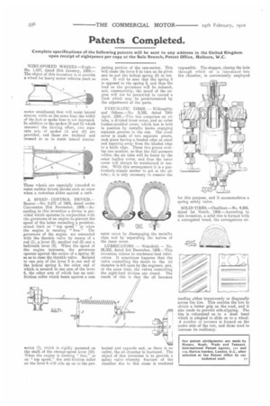
WIRE-SPOKED WHEELS.—Pugh.No. 1,637, dated 21st January, 1909.— The object of this invention is to provide a wheel for heavy motor vehicles (such as motor omnibuses) that will resist lateral strains, while at the same time the width of the hub or spoke base is not increased. In addition to the spokes (B and C) which transmit the driving effort, two separate sets of spokes (A and Al) are provided, and these are inclined and crossed so as to resist lateral strains.
These wheels are especially intended to resist sudden lateral shocks such as occur when a motorbus slides against a curb.
A SPEED CONTROL DEVICE.— Saurer.—No. 6,671 of 1909, dated under Convention 21st November, 1908.—According to this invention a device is provided which operates in conjunction with the governors of an engine to prevent the speed of the latter exceeding a predetermined limit on "top speed" or when the engine is running "free." The governors of the engine are connected with the throttle valve by means of a rod (1), a lever (3), another rod (2) and a bellcrank lever (4). When the speed of the engine increases, the governors operate against the action of a spring (8) so as to close the throttle valve. Secured to one arm of the lever 3 is one end of the helical spring 5, the other end of which is secured to one arm of the lever 6, the other arm of which has an anti. friction roller which bears against a cam sector (7), which is rigidly mounted on the shaft of the change-speed lever (10). When the engine is running "free," or on " top speed," the anti-friction roller on the lever 6 will ride up on to the pro. jecting portion of the cam-sector. This will cause the lever 6 to turn on its pivot and to put the helical spring (5) in tension. It will be seen that the spring 5 is opposed to the spring 8, and thus the load on the governors will be reduced, and, consequently, the speed of the engine will not be permitted to exceed a limit which may be predetermined by the adjustment of the parts.
PNEUMATIC TIRES, — Willoughby and Others.—No. 9,186, dated 19th April, 1909.—This tiro comprises an air tube, a divided inner cover, and an outer leather-studded cover, which last is held in position by metallic hooks engaging separate grooves in the rim. The inner cover is made of two separate pieces, each piece having a beaded edge as usual and tapering away from the beaded edge to a knife edge. These two pieces overlap one another, so that the full pressure within the air tube will be borne by the outer leather cover, and thus the outer cover will always be maintained in tension. With this arrangement it is a particularly-simple matter to get at the air tube ; it is only necessary to remove the Outer cover by disengaging the metallic clips and by separating the halves of the inner cover.
LUBRICATORS. — Wakefield. — No. 28,303, dated 3rd December, 1909.—This invention relates to condenser-feed lubricators. It sometimes happens that the valve controlling the steam to the oil chamber is left open by the engineer, and, at the same time, the valves controlling the sight-feed devices are closed. The result of this is that the oil becomes heated and expands and, as there is no outlet, the oil chamber is fractured. The object of this invention is to provide a safety valve whereby fracture of the chamber due to this cause is rendered impossible. The stopper, closing the hole through which oil is introduced into the chamber, is conveniently employed for this purpose, and it accommodates a spring safety valve.
SOLID TIRES.—Challiner.—No. 4,926, dated let March, 1909.—According to this invention, a solid tiro is formed with a corrugated tread, the corrugations ex
tending either transversely or diagonally across the tire. This enables the tire to obtain a better grip on the road, and it also tends to prevent side-slipping. The tire is vulcanized on to a steel band which is adapted to slide on to a wheel. A number of recesses is formed on the under side of the tire, and these tend to increase its resiliency.