


Patents Completed.
Page 32
If you've noticed an error in this article please click here to report it so we can fix it.
Complete specifications of the following patents will be sent to any address in the United Kingdom upon receipt of eightpence per copy at the Sale Branch, Patent Office, Holborn, W.C.
CARBURETTER. — Jouffret and Renee.—No. 11,742, dated 18th May, 1909.—This invention relates to carburetters of the type having an auxiliary fuel nozzle which is adapted to supply fuel direct to the induction pipe. According to the present invention, the auxiliary fuel nozzle extends to a higher level than the main fuel nozzle, and it is er closed in an air-tight chamber which is controlled by a spring-loaded ballvalve. With this arrangement, the auxiliary fuel nozzle does not, supply fuel to the induction pipe until a sufficient suction is obtained in the latter to lift the ball-valve off its seating. It will be seen, therefore, that the amount of fuel supplied by the auxiliary nozzle will more or less depend upon the area of the opening in the air-tight chamber and consequently upon the auction in the induction pipe.
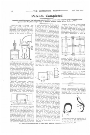
MOTOR PROPELLED LOCOMOTIVES.—Gebrtider Sulzer.—No. 12,030, dated 21st May, 1909.—(Patent of Addition to No. 28,040/1906.)—This invention relates to tho propulsion of locomotives and has particular reference to the system described in Specification No. 28,040/1906. In that specification, there is described a system of propal
Bien wherein two motors are provided, one operating as an auxiliary motor independently of the driving axle, arid serving to store compressed air for driving the main motor, and the other motor being of the internal-combustion type coupled to the driving axle and supplied with compressed air from a pump driven by the auxiliary motor. According to die present invention the main motor is arranged to drive an air pump which latter supplies sufficient air for the working of the main motor so long as the load
is within certain limits. In the diagram it will be seen that, the main motor is coupled to the axles of the locomotive; the auxiliary motor drives an air pump that is connected by means of a pipe to the main motor. A reservoir for compressed air communicates with this pipe. The main motor drives through suitable gearing a pump having both low.pressure and high-pressure cylinders. The pump driven by the auxiliary motor is adapted to supply sufficient compressed air for actuating the main motor when it is required to start the locomotive; the main motor then acts as a compressed-air motor. The provision of an air pump driven by the main motor has the advantage that, should the auxiliary motor fail, the driving motor is not necessarily thrown out of operation. Again, when the main motor is running normally the auxiliary motor may he run at very-low speeds or may even be stopped altogether.
LUBRICATING SYSTEM—Gardner and Another.—No. 22.205. dated 29th September, 1909.—This invention relates to that type of lubricating system in which the oil is collected in a suitable receptacle, at the bottom of the crankcase, and is redistributed to the hearings by means of a pump. It often happens that, when the vehicle to which the en gine is fixed. rolls about, the lubricant is dispersed about the crankcase, so that. an insufficient quantity is collected in the receptacle to supply the pump. In order to overcome this difficulty, a storage tank is provided which is interposed between the delivery side of the oil-pump and the pipe leading to the bearings which are to be lubricated. The operation of this apparatus is as follows. The storage vessel is filled with oil up to the level of its delivery orifice, so that, immediately the pump commences to act there will be a flaw of oil to the bearings. As the pressure increases in the system. the level of the oil in the storage tank will rise and so will compress the air entrapped above it., Should, however, the oil-pump momentarily cease to deliver oil to the storage tank, as, for example, when the vehicle is being badly bumped about the road, the reserve oil will be forced to the bearinga by the compressed air above it. The excess of oil in the system will cause the receptacle in the bottom of the crankcase to he flooded and the pump thus again to be supplied. The excess of oil will then he returned to the storage tank as the pressure in the system increases.
MOTOR RAILWAY CARS.—Roots and Heywood.—No. 11,384, dated 13th May, 1909.—This invention relates to means for transmitting the power from the engine to the bogies of motor-driven railway cars. The engine shaft drives, through a suitable clutch and a variablespeed gear, a second shaft on which is mounted a, slidable sleeve that carries two bevel wheels. These bevel wheels are adapted to engage a similar bevel wheel mounted on one end of a vertical shaft, so that this shaft may be rotated in reverse directions according to which of the bevels is in engagement. This vertical shaft extends down to the bogie frame, and it drives both axles by means of cardan shafts and suitable bevel gears.
TIRE LEVER—Lemon.—No. 20,424, dated 7th September, 1909.—This lever is particularly adapted to hold the outer
cover in a convenient position, while the security bolts or valves of a pneumatic
tire are being adjusted. The lever is provided with a looped-hook member which is pivoted thereto, and this hook is adapted to engage the beaded edge of the outer cover, so that the latter may be held clear of the rim as shown,