 1
1 2
2 3
3 4
4 5
5 6
6 7
7 8
8 9
9 10
10 11
11 12
12 13
13 14
14 15
15 16
16 17
17 18
18 19
19 20
20 21
21 22
22 23
23 24
24 25
25 26
26 27
27 28
28 29
29 30
30 31
31 32
32 33
33 34
34 35
35 36
36 37
37 38
38 39
39 40
40 41
41 42
42 43
43 44
44 45
45 46
46 47
47 48
48 49
49 50
50 51
51 52
52 53
53 54
54 55
55 56
56 57
57 58
58 59
59 60
60 61
61 62
62 63
63 64
64 65
65 66
66 67
67 68
68 69
69 70
70 71
71 72
72 73
73 74
74 75
75 76
76 77
77 78
78 79
79 80
80 81
81 82
82 83
83 84
84 85
85 86
86 87
87 88
88 89
89 90
90 91
91 92
92 93
93 94
94 95
95 96
96 97
97 98
98 99
99 100
100 101
101 102
102 103
103 104
104 105
105 106
106 107
107 108
108 109
109 110
110 111
111 112
112 113
113 114
114 115
115 116
116 117
117 118
118 119
119 120
120 121
121 122
122 123
123 124
124 125
125 126
126 127
127 128
128 129
129 130
130 131
131 132
132 133
133 134
134 135
135 136
136 137
137 138
138 139
139 140
140 141
141 142
142 143
143 144
144 145
145 146
146 147
147 148
148 INTEGRA1 'ANKER BY THOMPSON
Page 80
Page 81
Page 82
If you've noticed an error in this article please click here to report it so we can fix it.
Many Advanced Features Combined in Specially Built Rear-engined Outfit for High-speed Operation
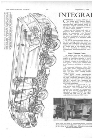
CAPABLE of carrying 4,000 gal. of any liquid with a specific gravity of up to 0.847, a rear-engined maximum-load eight-wheeled tanker of light-alloy integral construction will be one of the most outstanding Commercial Motor. Show exhibits.
Known as the Europa and built by Thompson Bros-. (Bilston), Ltd., Bilston, Staffs, in conjunction with Leyland Motors, Ltd., for the B.P. company, the tanker is designed to provide a high degree of stability at its maximum speed of 45 m.p.h.
The use of Dunlop leaf-air springs on the two steering axles has overcome steering and suspension difficulties that might have arisen from the distribution of weight with a rear-engined layout. Ease of handling is enhanced by Westinghouse air-pressure-assisted steering.
Entry Through Centre The makers state that the vehicle is• stronger and lighter than conventional tankers of equivalent capacity. A novel feature of the cab is that entry into it is through a hatch in the middle of the front panel. Sliding side windows and a roof hatch are available as emergency exits.
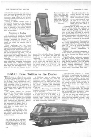
A wrap-round windscreen with a thin centre pillar gives a wide range of vision. The Chapman adjustable aircraft-type seats are fitted with Delaney Gallay safety harnesses.
Other details include high-powered wipers and large-capacity washers, heating and ventilating equipment and an optical rear-view system. In conformity with B.P, practice, the Compagnie de l'Esthetique Industrielle were employed as styling consultants.
The vehicle is equipped with a Leyland power pack similar to that of the Atlantean. This is designed for easy removal for overhauls or replacement. Of the new Leyland Power-Plus type (described on pages 172-175), the engine develops 200 b.h.p. (net) at 2,200 r.p.m. and 548 lb.-ft. torque at 1,200 r.p.rn. Fuel is supplied from a 36-gal. tank on the near side of the vehicle. There is also the hydraulic fluid of the hydrostatic-drive system of the pumping equipment.
Power is transmitted through a Leyland Pneumo-Cyclic four-speed gearbox (giving two-pedal control) to the second rear axle, the first axle being of the trailing type.
An Eaton two-speed driving axle is employed to give an overdrive-tap gear for use on return runs with an empty tank. The overall final-drive ratios, including the angle-drive gears, are 5.55 and 7.6 to 1.
Air-pressure braking is applied to the first front axle and to both rear axles, whilst the hand brake is assisted by air pressure.
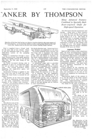
The shackles of the front leaf springs are fitted to underslung brackets bolted to the main longitudinal box-section runners of the integral tank structure.
A 10-in, two-convolute bellows is fitted above each leaf spring in line with the beam axle and inboard of the leaf centre line. Although the front and rear bellows are of the same diameter, the static height of the bellows of the first axle is 51 in., compared with a static height of 61 in. for the bellows of the second axle.
The effective area of the forward bellows is therefore greater than the area of the bellows of the second axle, and the springs can accommodate the higher load without an increase in pressure.
A single levelling valve is employed to obviate diagonal loading, and this is -fitted to the front of the first axle on the near side. The arm is connected to a plate under the leaf spring, which is also used for mounting
the shock-absorber arm. Armstrong levertype dampers are employed on all axles.
To counter braking torque reaction, the first front axle is equipped with radius arms. These are anchored to the centre of the axle and linked to brackets on the frame runners adjacent to the mountings of a channel-section cross-member at the front. Metalastik flexible bushes are used throughout.
A cylindrical surge tank is provided for each -suspension system. The connecting pipe is equipped with an isolator valve to stabilize pressure variations between the two tanks. The tanks are mounted longitudinally between the axles, whilst the reservoir is in the cab.
It is believed that the suspension represents the first application of air springs to the twin steering axles of a multi-wheeled vehicle, and, as expected, a number of difficulties had to be overcome to match the combined characteristics of the leaf springs and air bellows to load requirements. The first front axle has asymmetric leaf
springs. These give a beam location 3 ft. from the front spring eye and 2 ft. 2 in. from the rear eye, the total spring length being 5 ft. 2 in. The beam of the second axle is arranged symmetrically in the centre of 4-ft. 4-in. springs.
Of the oscillating-beam type, the rear suspension is based on leaf springs with a length of 4 ft. The hanger brackets are outrigged from the runners. Michelin Metallic C.20 tyres are fitted.
Argonarc Welded
Built of NS 6 5J32-in,-thick aluminium alloy, the basic six-compartment integral structure is argonarc welded throughout. An extremely rigid layout is provided by welded-in box-section runners at the top and bottom of the structure on both sides, These are braced internally by box-sectioned stiffeners welded to the compartment divisions, The main loads are not therefore transmitted to the panels of the tank.
Lower runners of the structure are extended forward to support the cab and the forward shackles of the first front axle, and extensions to the rear, of the structure are employed for mounting the engine cover.
Approximate depth of the runners is 8 in., but the depth of the lower runners is increased to 10 in, over the driving axle. The engine-mounting brackets are undergiung from these sections.
The shape of the tank is designed to eliminate the need for cleansing rings and give full drainage of the liquid. The minimum angle of the sides and ends 'is 10 degrees. REAR VIEW LENS
The shape of the lower part of the structure is in the form of a shallow trough and the main runners are blended to the trough sides on the inside to simplify construction and enhance rigidity.
Four cross-bracing members of similar trough form are employed to stiffen the structure torsionally. A flitch plate is
welded to the runners on each side to cover the joints between the two "sections, and the outer flange members of the bearers are plug welded as well as continuously welded in line with the division plates of the tank.
Access to shackle bracket bolts is provided by apertures on the inside of the runners. These are locally stiffened by welded-in steel liners. Zinc-chromate paint is. applied to the mating surfaces of the two metals to obviate the possibility of corrosion.
Resistance to Bending At a number of points of increased stress concentration, aluminium distance pieces arc. inserted in the runners to increase 'resistance to bending, :Art example is the section of the off-side runner on which the steering box is mounted.
Front anchorage for . the lower runners is provided by. two. light-alloy tapered box-section members which form the pillars of the driver's entrance hatch, whilst the main 'structure is extended at the top to form the cab roof. The cab structiire is further stiffened by a. boxsection waist rail, and is internally lined with pleasant upholstered aluminium panelling.
External panelling is formed by a onepiece glass-fibre moulding impregnated with epoxy resin. Plastics mouldings are also used for the side panels below waist level and the engine cover. Side areas of the tank are finished in B.P.
green, white and yellow, livery. Fireproof bulkheads at the front and rear are based on an angle-section light-alloy framework.
The vehicle has a wheelbase of 16 ft. 10 in., front and rear tracks are 6 ft. 1+ in. and 5 ft. 111 .in. respectively, and the overall length is 29 ft. 11 in. The height is 8 ft. 4 in., and the width 7 ft. 104 in.' Specially designed for the vehicle, the Barr and Stroud optical rear-view unit supplements conventional driving mirrors and gives a 40° cone of sight to 3° above the horizon and to within 8 ft. of the rear of the vehicle at ground level.
A special duct is built along the top of the vehicle under the walkway to house the lens system, to which the view is relayed through prisms. At the front of the duct the image is received by a. graticulated screen, with 6 in. of lateral head freedom, and reflected on to an adjustable 6-in, diameter driving mirror which is mounted in the normal position.
The instrument panel is illuminated by an Electro luminescence cold-light systern supplied by Thorn Electrical Industries, Ltd. This is of the type developed for aircraft to eliminate glare and reflection. Current consumption is Heating and ventilating equipment it of the Smiths twin-unit type. The pipes are carried between the double skin of the cab.
Liquid-handling equipment comprises an Avery Hardoll meter and bottomloading system with quick-acting couplings, and a Goodyear 150-g.p.m. pump. A filter and air separator are also of Avery Hardoll manufacture. Safety features include an engine exhaust system with a centrifugal flame trap.