


A Lockable Brake Compensator
Page 70
If you've noticed an error in this article please click here to report it so we can fix it.
A Xsume. of Recently Published Patent
Specifications
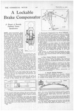
MBII brake-compensating device 1 described in patent 'No. 332,992, of C. M. Linley, 9, Hamilton Road, Highbury, London, N.5, is one in which a complete and instantaneous compensation between four brakes can be made, and by the tightening of a single bolt the four brakes can be locked to act as if there were no compensating mechanism. The illustration in the patent specifica tion does not make the construction of the device very clear, but having actually seen and handled a model we are able to give a more practical description of its working.
At any convenient part of the chassis a cross-haft le fixed. This shaft need not rotate, but may be
fixed at its ende. Rotatably mounted on this shaft are four lengths of tube extending from the
outer ends of the shaft towards a convenient place where: a pull rod can operate from either hand-lever or foot-lever. A pull rod (3) is connected to the central lever of a group mounted on the cross-shaft. This lever resembles those that lie by the side of it, but is provided with extending bosses ,(A and B) and has a plain hole instead of the segmental slots shown in the other levers of the group. To A is attached the pull-rod (I) from the pedal, whilst B carries the pivot of a whipple-tree or compensating beam (C). To the ends of this beam are pivoted the push links (D and Dl), each of which pushes a smaller whipple-tree (E). Four of the groups of levers are provided with segmental slots, as shown, and a clamping bolt (1') is capable of locking the whole group of levers together so that they all move as one solid mass when required, thus cutting out all compensating action.
To the outer ends of the tubes which rotate on the crossshaft, the levers G, Gl, and H and II4 are secured. To these levers the pull rods which lead to the front and rear brakes are attached.
In operation, when pressure is applied to the pedal, it pulls the central of the five fiat levers forward, the result of which is that, through the main whippletree (C), balance of power takes place between the levers which control the brakes on the right and left-hand side of the vehicle, and through the small whippletree (B) a balance between front and rear brakes is obtained.
While pressure is maintained on the pedal, the locking bolt is then tightened, thus locking the segmentally slotted levers to the central one and causing all brakes to operate as if there were no compensating device. A rough adjustment at the ends of the brake rods can be provided so that the compensation can be kept within the limits of the segmental slots.
c48
A Pneumatic Suspension for Front Wheels.
AN interesting invention is described in patent No. 333,119, in which appears the name of G. L. R. 3'. Messier, already known in connection with pneumatic suspension. The illustration indicates an adaptation of the plan to the landing wheels of an aeroplane, but the specification mentions the fact that the invention might, with some modifications, be applied to the steerable front wheels of various types of motor vehicle.
When applied to a motor vehicle, the arm (B) would represent the front axle, and would carry a vertical cylinder mounted centrally with the wheel. What takes the place of the usual stub end is a cylinder having a -trunnion at each side, one small and one large. On these trunnions are mounted the .ball bearings which support the wheel, the steering arm being attached to the edge of the larger trunnion.
The cylinder to which the axle is connected can slide 'within the trunnioned cylinder, air under pressure forming the spring. The cylinders actually form the pivot on which the wheel steers.
A New Foden Chassis Arrangement.
THE name of E. It. Foden and Fodens, Ltd., appear in patent No. 333,101. As the specification does not make it very clear as to what constitutes the invention, we append the only two claims. (1) In a steam-driven vehicle as claimed in our prior patent No. 227,611, the combination of an engine unit suspended beneath the chassis and having the cylinders arranged transversely to the length of same, with a cardan shaft disposed in alignment with the engine crankshaft and
adapted to be•direetly coupled thereto. , (2) Improved steam-driven vehicles substantially as described and as illustrated.
A Simple Spring Damper.
SPECIFICATION No. 333,025, by E. Bagnall, a British subject, of 6411, Tenth Avenue, Kenosha, U.S.A., relates to a simple form of spring damper which, it is claimed, can be attached to the springs of a vehicle while they are in
place. It is also claimed that by inducing friction between the leaves of the springs the objectionable tendency to oscillate, especially when balloon tyres are used, can be greatly reduced.
The device consists of a strap having an open gap which enables it to be placed on the spring Without removing it. A plate is placed through the strap and a setscrew produces the required friction.
It will be noted that one end of the plate hears directly upon the spring leaves, whilst the setscrew provides the
means for varying the amount of damping action.