


• Coritintiotisspray' injection
Page 66
If you've noticed an error in this article please click here to report it so we can fix it.
A CCORD1NG to patent No. 817,677, .rt the advantages, of petrol injection are offset by the cost of injection pumps and the need to provide separate fuel pipes to the inlet duct of each cylinder. By the use of a continuous-spray system shown in the patent, it is Claimed that the engine performance is comparable to that given by injectionin timed. spurts: (Bendix Aviation Corp., South Bend, Indiana, U.S.A.)
For this design the inlet ducts to all cylinders are separate until they meet at a central point; the drawing shows this arrangement on a V8 engine. In the central chamber is a spray nozzle (1) having a jet directed towards each duct. Actually there are three jets to each; these open in succession in accordance with the suction in the chamber. In addition, there are idling jets for providing a rich mixture. The patent shows the detail construction of the spray unit and of the pressure-controlled member that selects the Dumber of jets used.
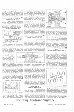
A SELF-LIMITING HYDRAULIC PUMP
HYDRAULIC pumps, such as those used for power steering systems, are not required to have a large output at high speed. A pump in which the action is suspended at speed by a centrifugal mechanism is shown in patent No. 816,967. (W. Briggs and Burman and Sons, Ltd, Wychall Lane. King's Norton, Birmingham, 30.)
The pumping mechanism is of the radial eccentric-vane type, the vanes (I) touching the casing at one side and moving away at the other to form a pumping space (2). The inlet and outlet ports are located at 90 degrees from these two positions.
The invention consists of the provision
of pressure-release ports (3) which allow the output to. return to the intake side. Normdlly these are closed by a sliding valve (4) and are therefore inoperative. But, as the rotational sPeed. rises, the valve is moved to the right, by a centrifugal ball governor (5) against" the-force of a central spring.
AlUTONIATIC CHAS$IS
• LUBRICATION: •
A. PUMP .for delivering a . small' but regular charge. of lubricant is .shown in patent No. 816,836. It is intended for lubricating a large number of points on a vehicle chassis or on a machine tool. The pump is driven by the gearbox or by the speedometer cable so that it works only when the vehicle is in motion. (Tecalemit, Ltd., Great West Road, Brentford, Middlesex.)
The drawing shows the pump included in the drive to the speedometer, the cable entering at the end (I) and continuing from the other end. A primary gear (2) is driven by the cable and engages with a worm wheel (3).
The worm wheel drives, via a double spur reduction gear (4), a snail cam (shown dotted at 5). A one-way clutch is incorporated to prevent the cam being driven backwards when the vehicle is reversing.
In operation, a rocker (6) is slowly lifted by the cam until it snaps over the lip under spring load. This return stroke operates a plunger pump (7) which delivers a charge of lubricant to the distribution point.
AIR SUSPENSION BOGIE
APNEUMATIC suspension. system described in patent No. 817,6S9employs an unusual means of locating the axles. (Maschinenfabrik AugsburgNUrnberg A. G., Ntirnberg, Germany.)
The drawing shows the layout applied to a vehicle with twin rear wheels. The axle-casing (1) is located by pairs of transverse arms (2) jointed to the casing by short connecting-rods (3). On the other side, similar arms (4) are directly pivoted to the casing, the assembly being rather like a conventional spring-shackle design.
The arms are fixed to rubber-bushed sleeves (5), to which are attached longer arms (6). These support the load by compressing the air-springs (7) against the underside of cross-members. On each side there is one air-spring in front of the wheels and one behind them.
The rubber-bushed mountings are carried on a pair of longitudinal tubes (8) which form the main frame of the vehicle, the cross-members being attached to them. Another scheme shows box girders for the frame.
TURBOCHARGER CONTROL DATENT No. 816,953 deals with
turbocharged engines. The subject of the patent is a method of governing such engines. (A. Buchi, Archstrasse 2, Winterthur, Switzerland.)
The drawing shows one of several schemes mentioned; in this case it is applied to a six-cylindered engine. The exhaust-driven blower (I) delivers its output through a duct containing a throttle valve (2). The injection pump is controlled by a pneumatic cylinder (3) which is responsive to the quantity of air being delivered. To IlIchieve this response, one end of the cylinder is piped to the duct at the point 4 and the other end to the middle of the venturi (5).
Any increase in engine load results in an increase in the pressure difference; this in turn acljus s the pump to increase the fuel supply -ind so prevent a drop in speed. The throttle valve is governed also by a pneumatic unit (6) but as it can be moved by the accelerator pedal (7) the driver has overriding control.
BETTER BRAKE DRUMS
TO obtain good friction characteristics and long wearing life, it is proposed in patent No. 816,169 to spray the inside of brake drums with metallic molybdenum. The patent comes from General Motors Corp., Detroit, U.S.A.
TYRE VULCANIZING
I-1 A MACHINE for effecting repairs by vulcanizing while the tyre is in place on the wheel is shown in patent No. 816,339. The device is attached to the tyre and provides the heat, whilst the necessary pressure is applied by inflation of the tyre. (0. and W. Gruber, Rosenheimerstrasse 17, Munich 8, Germany.)