


Goods Handling Scheme
Page 51
If you've noticed an error in this article please click here to report it so we can fix it.
AUNIT for assisting the loading and unloading of a lorry at a dockside or a works dispatch bay is shown in patent No. 895,713. The device disclosed consists of a Movable trolley, the height of which can be readily adjusted to suit various levels of lorry. (Fisher and Ludlow Ltd„ Bordesley Works, Clyde Street, Birmingham, 12.)
In the drawing, a lorry platform is shown in dotted lines at 1. A Pair of castored trolleys (2 and 3) are joined to form a single unit on the top of which arc guide channels (4).
In the channels runs a wheeled truck (5) upon which the load is brought. The truck, with its load, is then rolled on to the lorry and secured thereto.
Height adjustment is given by a pair of hydraulic jacks (6). One is provided at each side. so that sideways tilt of the lorry can easily be accommodated. The jacks press down on pivoted feet (7) which help if the ground be uneven. Both the feet and the jacks can be swung clear of the ground when not in use.
Vehicle Cleaning Machine
ACLEANING unit described in patent No. 902,046 employs the usual type of rotary brushes, but the vertical spindles thereof can be adjusted to suit all types and sizes of vehicle. The patentee is Spark brook Developments Ltd., Vulcan Works, Stratford Road, Birmingham, 11.
Steering-wheel Insulation
IF the steering wheel of a vehicle is connected rigidly to the steering mechanism, it is almost inevitable that road and frame shocks are transmitted to it. This tends to increase driver fatigue and in patent No. 896,550 is shown a scheme for insulating the wheel to some degree. (Ford Motor Co. Ltd., 88 Regent Street, London, WA.) The draw ng shows the essential part of the inven ion; this comprises a forked coupling (1) engaging with rubber-bushed holes in a plate (2). The fork is a sliding fit in the bushes so that axial vibrations are completely eliminated. Not only does the joint cushion road shocks but it acts also as a universal joint to accommodate small errors of alignment.
An alternative arrangement gives provision for allowing axial movement between the steering wheel shaft and the steering gearshaft. This is achieved by arranging for the forked coupling to be a sliding fit in the rubber-bushed plate.
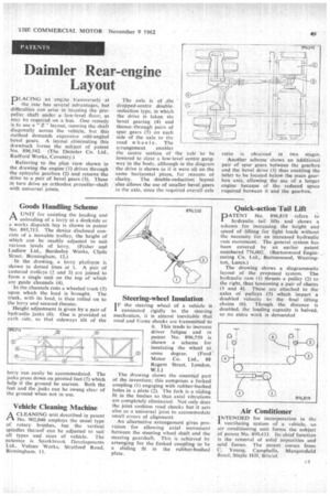
Quick-action Tail Lift
PATENT No. 896,819 refers to hydraulic tail lifts and shows a scheme for increasing the height and speed of lifting for light loads without the necessity for an increased hydraulic ram movement. The general system has been covered by an earlier patent numbered 776,002. (Burtonwood Engineering Co. Ltd., Burtonwood, Warrington, Lancs.)
The drawing shows a diagrammatic layout of the proposed system. The hydraulic ram (1) thrusts a pulley (2) to the right, thus tensioning a pair of chains (3 and 4). These are attached to the axles of pulleys (5) which impart a doubled velocity to the final lifting chains (6). Though the distance is doubled, the loading capacity is halved, so no extra work is demanded
Air Conditioner
I NTENDED for incorporation in the
ventilating system of a vehicle, an air conditioning unit forms the subject of patent No. 899,433. Its chief function is the removal of solid impurities and acid fumes. The patent comes from C. Young, Campbells, Mangotsfield Road, Staple Hill, Bristol.