


An Exhaust-driven Supercharger
Page 82
If you've noticed an error in this article please click here to report it so we can fix it.
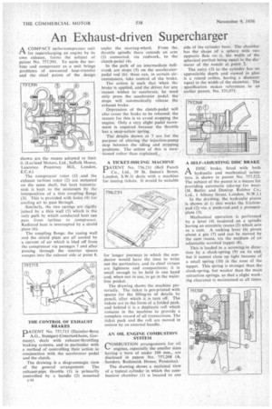
PAA COMPACT turbo-compressor unit for supercharging an engine by its own exhaust, forms the subject of patent No. 757,591. To unite the turbine and compressor as a unit brings problems of unwanted heat-transfer and the chief points of the design
shown are the means adopted to limi it. (Ley land Motors. Ltd., Suffolk House Laurence Pountney Hill, London E.C.4.) The compressor rotor (1) and the exhaust turbine rotor (2) are mounted on the same shaft, but heat transmission is kept to the minimum by the interposition of a thin coupling flange (3). This is provided with holes (4) for cooling air to pass through.
Similarly, the two casings are rigidly joined by a thin Wall (5) which is the only path by which conducted heat can pass from turbine to compressor. Radiated heat is intercepted by a shield plate (6).
The coupling flange, the casing wall and the shield plate arc all cooled by a current of air which is bled off from the compressor via passages 7 and after passing through the interior spaces escapes into the exhaust side at point 8.
THE CONTROL OF EXHAUST BRAKES
PATENT No. 757,713 (Daimler-Benz A.G., Stuttgart-Untcrturkheim, Germany), deals with exhaust-throttling braking systems, and in particular with a method of controlling their action in conjunction with the accelerator pedal and the clutch.
The dra‘wing is a diagrammatic view of the general arrangement. The exhaust-pipe throttle (1) is primarily controlled by a handle (2) mounted c44 under the steering-wheel. From the throttle spindle there extends an arm (3) connected, via rodwork, to the clutch-pedal (4).
In the path of an intermediate bellcrank are stops (5) on the acceleratorpedal rod (6); these can, in certain circumstances, take control of the brake.
The action is such that when the brake is applied, and the driver for any reason wishes to accelerate, he need only press the accelerator pedal; the stops will automatically release the exhaust brake.
Depression of the clutch-pedal will also cause the brake to be released: the reason for this is to avoid stopping the engine. Only a very slight podal movement is required because the throttle has a snap-action spring.
The details shown at 7 are for the purpose of altering the injection-pump stop between the idling and stopping positions. The action of this is mentioned rather than explained,.
A TICKET-ISSUING MACHINE
PATENT No. 756.231 (Bell Punch Co., Ltd., 39 St. James's Street, London, S.W.1) deals with a machine for issuing tickets. it would be suitable
for longer journeys in which the conductor would have the time to write out the particulars, and its chief virtues are lightness and compactness; it is small enough to be held in one hand and, when not in use, to go in the waistline pocket.
The drawing shows the machine pictorially. The ticket is prc-printed with spaces for the filling-in of details by pencil, after which it is torn off. The tickets are in the form of a folded pack. and behind it is a duplicate roll which remains in the machine to provide a complete record of all transactions. The ticket pack and the roll are moved in unison by an external handle.
AN OIL ENGINE COMBUSTION SYSTEM
COMBUSTION arrangements for oil engines, especially the smaller sizes having a bore of under 100 mm., are disclosed in patent No. 757,268 (A. Sanders. Redinnick House, Penzance).
The drawing shows a sectional view of a typical cylinder in which the combustion chamber (I) is located to one side of the cylinder bore. The chamber has the shape of a sphere with two opposite flats on it. the width of the spherical portion being equal to the diameter of the nozzle at point The entry (3) to the cylinder has no appreciable depth and viewed in plan is a round orifice, having a diameter equal to the width of the chamber. The specification makes references to an earlier patent, No. 531,075.
A SELF-ADJUSTING DISC BRAKE
ADISC brake, fitted with both hydraulic and mechanical actuators, is shown in patent No. 757,522. The subject of the patent is a means for providing automatic take-up for wear. (IL Butler and Dunlop Rubber Co., Ltd., 1 Albany Street, London, N.W.1.)
In the drawing, the hydraulic piston is shown at 1; this works•the frictionpad (2) via a push-rod and a pressure. plate (3).
' Mechanical operation is performed by a lever (4) mounted on a spindle having an eccentric recess (5) which acts as a cam. A rocking lever (6) pivots about a pin (7) and can be moved by the cam recess, via the medium of an adjustable screwed tappet (8).
This is loaded in a screwing-in direction by a clock-spring (9) on its end, but it cannot close up tight because of a small spring (10) in the nose of the tappet. This spring is stronger than the clock-spring, but weaker than the main retraction springs, so that a slight work-, ing clearance is maintained at all times.