


An Improved Trailer Pivot Bearing
Page 84
If you've noticed an error in this article please click here to report it so we can fix it.
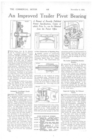
FROM Fodens, Ltd., R. W. Whittle and E. Twemlow, all of Elworth Works, Sandbach, Cheshire, comes patent No. 416,987 describing improvements in the design of trailer pivot bearings, the objects of which are to prevent side sway and to improve steering. In an accompanying drawing, which shows a front view of the trailer, a spherical bearing (3) forms the uniVersal member. Attached to the cup of this ball are four leaf-springs, of which two only (2 and 4) are shown, the other pair being disposed in a fore-andaft direction. Attached to the chassis is a large ring (1) which is intended to come into contact with the crossshaped spring and thus take the load in any direction in which side-sway would commence.
• The towing bar is made of two members, one leading to the ball-socket, whilst the other is joined to the wheel axle. The result is that the towing bar does not fall to the ground when the tractor is removed.
Automatic Centrifugal Clutch Refinements.
PATENT No. 415,029, communicated by Automotive Patents Corporation, 342, Madison Avenue, New York, U.S.A., deals with detail improvements in the design of centrifugally „operated clutches. With a clutch of this description it is usual to arrange for manual operation, in addition to the automatic action. . At high engine speeds, however, it may be difficult to operate the clutch manually owing to the centrifugal action increasing as the square of the speed, and the chief feature of this invention is the provision of a stop (2), on the centrifugal weights (1), which comes to rest on the ring (3).
The patentee claims that this stop limits the force required to free the clutch against the centrifugal action, but just how this occurs is not made very clear; the action appears to us to limit only the pressure applied to the plates, the manual control having, in any case, to overcome the automatic force.
c54 A New Construction of Sparking Plug.
A NOVEL method of constructing 1-1.and assembling a sparking plug is described in patent No. 417,097 by the Champion Spark Plug Co., Toledo, Ohio, U.S.A. The improvement lies
principally in the method of sealing the assembled plug. Referring to the drawing, the insulating sleeve is held down on its seating by a ring of soft powder (3) above which is another ring of aluminium (2). This ring is in the
form of aluminium powder when assembled, and a finishing ring of copper (1) is placed on top. After assembly the plug is placed in'an alternating magnetic field powerful enough to melt the
aluminium powder by self-contained induced current, and thus fuse it into• a solid ring. By this means the plug is, in effect, sealed by casting in the component parts.
The Latest Combustion-chamber Practice.
1N patent No. 417,221 F. A. Perkins, 17, Queen Street, Peterborough, describes progress in the design of combustion chambers for oil engines. In this invention, the chamber is substantially cylindrical io form, and is connected to the cylinder by a tangential passage. The injection nozzle is located in this passage, and the nose is arranged to direct the fuel partly into the combustion chamber and partly down towards the cylinder, the major supply, however, going upwards. A feature is the accessibility of both the combustion chamber and the injection nozzle, the latter being housed in a tube in the water space.
Improved Cooling for Exhaust Valves.
STATED to be eminently suitable for Ouse in direct-injection oil engines, " a novel combination of inlet and 'exhaust valves is shown in patent No. 416,406 by C. E. M. March, Penny Oak, Fulmer Road, Gerrard's Cross. The drawing shows the arrangement, comprising a mushroom valve for inlet purposes, seating in a piston-like exhaust valve (1). This exhaust valve rises to uncover an annular port leading to the exhaust passage (2), whilst the inlet valve draws its supply from passage 3. The inlet valvP must, of course, move with the exhaust valve, the necessary relative movement having to be provided by a differential cam action. The drawing makes this clear.
The claims to improved cooling are based on the fact that the incoming air passes through the tubular exhaust valve. Powerful return springs are necessary on this valve, owing to the tendency of the explosion to lift it from its seat.