


Ingenious Features in
Page 70
Page 71
If you've noticed an error in this article please click here to report it so we can fix it.
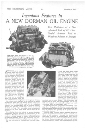
A NEW DORMAN OIL ENGINE
ALTHOUGH, in the main, oilengine design has reached a stage where the principles involved in almost every type are the same, there is, nevertheless, welcome individuality in contemporary layout. In the new Dorman six-cylindered engine, made by W. H. Dorman and Co., Ltd., Stafford, there is a number of features peculiar to the design in question, and it is interesting to note that, whilst every effort has been made to ensure a thoroughly robust unit, a careful eve has, nevertheless, been kept upon the weight question. To this end, the crankcase, which is 14 ins, deep. and the sump are of aluminium, whilst the cylinder heads are cast in Hiduminium, being formed in two groups of three.
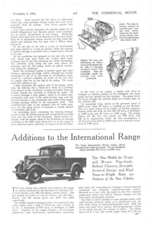
The cylinder block is secured to the crankcase by means of long bolts which pass right through the two components and secure the main-bearing caps for the crankshaft journals. The bolts are passed into the crankcase through the top and they are located at the bottom by screwed shanks 2 ins. long. They are pulled down to shouldered portions of the bolts lying below the top face of the crankcase.
Screwed plugs locate the bolts in an upward direction, extensions of the bolts retaining the cylinder block in the usual way. This form of construction is ingenious, because it allows a certain amount of relative movement due to the differing expansion rates of iron, aluminium and steel, at the same time maintaining a high degree of rigidity.
The bore and stroke are 101.6 mm. and 130 mm. respec c40 tivelv, the bores being formed by liners of nitrided cast iron. Instead of being pressed into the top, these liners are inserted from the bottom of the cylinder block, a flange on the outer diameter of each liner engaging with a recess in each bore, so that when the cylinder block is mounted on the crankcase, all the liners are secured in such a manner that longitudinal expansion can take place without causing harm.
The crankshaft is a high-tensile steel forging, machined to fine limits. There are seven main bearings of 3i-in. diameter, and the crank pins are of 2i-in. diameter, the cores of both the pins and the main shaft being machined out to reduce weight. The Fl-sectioned connecting rods are made from steel stampings and the bigends are equipped with steel-shell bearings into which white-metal liners are centrifugally cast.
In each small-end there is a phosphor-bronze bush. Foul rings above the gudgeon pin form the pressure seal on the aluminium-alloy pistons, and one scraper ring on the skirt helps to minimize the quantity of oil passing into the combustion chambers.
Following usual Dorman practice, overhead valves are operated by push-rods and rockers from a camshaft con tained in the crankcase. Although the layout of the valve gear is planned on straightforward lines, there is cne feature worthy of mention ; we refer to the decompressing device. Passing through each valve cover is a shaft which controls three screwed pins coupled together by arms and links. Each screwed pin lies above an inlet-valve rocker and, when partially rotated, causes the valve to be depressed from its seating. Two levers operate this mechanism.
As we have already indicated, the cylinder heads are of R.R.50 Iliduminium and Ricardo patent swirl chambers are, of course, incorporated in the design. Naturally, special valve seats have to be inserted into the alloy head ; these are of aluminium bronze screwed on their outer diameters and. inserted into the head with a .002-in, interference fit.
On the off side of the unit is a pair of three-branch inlet pipes joined by a large air cleaner, whilst the exhaust is emitted through a manifold with a single-branch take-off at the rear.
All the auxiliaries are grouped on the near side of the unit. Spiral spur gears drive the various shaft lines, a timing case at the rear enclosing the whole mechanism. The camshaft, lying along the near side, drives the exhauster and the fuel pump, which are placed tandemwise along the crania-age.
Below the crankshaft pinion is another spiral spur gear driving a gear-type oil pump, which, although not exactly submerged in the oil in the sump is, nevertheless, maintained in a primed condition by virtue of the fact that the supply pipe lies at the top of the pump. The sump holds four gallons of oil.
A filter surrounds the suction side a the pump, whilst from the delivery side a bleed-off is taken to a pressure filter housed in the crankcase, it being accessible from the outside without the necessity of draining the sump. Oil is forced through a main gallery, which is in direct communication with each of the main-bearing caps, and the big-end journals of the connecting rods receive:their supply
through passages drilled in the crankshaft itself. The overhead-valve gear is also supplied with oil under pressure, and the pump serves to maintain a trough around the camshaft, full of oil.
An interesting point concerning the filtering arrangements is that the lubricating-oil and oil-fuel filters are both built into the walls of the crankcase. Being formed integrally with the engine, there is less likelihood of damage occurring to the filter units themselves or to the pipes—a most important point, especially in respect of the fuel filter.
At the front of the engine, a duplex belt drive is arranged to embrace pulleys on the crankshaft, the water pump and fan spindle and the dynamo. The pump forces the water through the cylinder heads to a header pipe on the exhaust side.
The maximum b.h.p. occurs at the governed speed of 2,400 r.p.m. when 90 b.h.p. is available at the flywheel. This is a good output for an engine of 6.3-litre capacity. Farther down the scale we find that 45 b.h.p. is developed at 1,000 r.p.m. and 64 b.h.p. at 1,400 r.p.m. The torque figures for the last two speeds are 236 lb.-ft. and 240 lb.-ft. respectively, whilst the fuel consumption is .38 pint per b.h.p.-hour at 1,000 r.p.m. and .4 pint per hour at 1,200 r.p.m.