


Dennis Introduces A New Oil Engine
Page 59
If you've noticed an error in this article please click here to report it so we can fix it.
AFTER considerable experience in the behaviour ot oil engines in passenger and goods chassis, the directors of Dennis Bros., Ltd., Guildford, have decided to produce their own engine in which the premier requirements to be met are sweet and silent running coupled with low maximum pressures, so as to give long life for the mechanical parts. To attain these ends a comparatively low compression ratio is essential, but, at the same time, fuel economy must be studied.
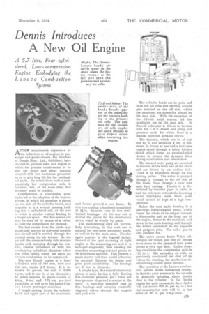
Consideration of combustion principles led to the adoption of the Lanova system, in which the atomizer is placed on one side of the cylinder barrel, and opposite to it a venturi opening leading into a cylindrical cell, at the end of which is another venturi leading to a larger air space. The last-named cell may be shut off by means of -a valve, to raise the compression for starting.
The fuel stream from the pintle-type single-hole sprayer is delivered towards the air-cell and is carried through the venturi along the air stream. In the air cell the comparatively rich mixture ignites and, emerging through the yenturi, creates turbulence in both the overlapping cylindrical chambers below the valve heads, where the extra air enables combustion to be completed.
The knew Dennis engine is a fourcylindered unit of 110 mm. bore and 150 mm. stroke (5.7 litres). It is intended to govern the unit at 2,000 r.p.m. and to use it, as an alternative to petrol engines, in goods chassis of 4-ton, 5-ton and 7-7i-ton pay-load capacities, as well as in the Lance-Four and Lancet passenger machines.
A single casting forms tha cylinder block and upper part of the crankcase, and houses pressed-in wet liners. In this iron casting a hardened crankshaft of 3i-in. diameter runs in five stetlbacked bearings. At the' rear end is carried the pinion for the distribution drive, which is wholly by gears.
The main-bearing caps are particularly interesting, in that each one is secured by two outer secondary studs, as well as by the main ones. Novelty again appears in the big-end design. Instead of the spilt occurring at right angles to the connecting-rod axis. it is arranged diagonally, thus allowing the complete connecting rod and piston to be withdrawn upwards. This permits a much shorter rod than would otherwise be required, lightens the design and gives good accessibility. The bearings are 31 ins, in diameter.
A simple type, flat-topped aluminium piston is used, having a fully floating 2-in.-diameter gudgeon pin ; there are four pressure rings and a scraper in the skirt. A cast-iron camshaft runs in five bearings and actuates vertically disposed valves through flat tappets and push rods. The cylinder heads are in pairs and have the air cells and starting control gear inserted on the oft side, whilst the atomizers are accessibly placed on the near side. With the exception of the 12-volt axial starter, all the auxiliaries are on the near side. A Reavell exhauster is driven in tandem with the C.A.V.-Bosch fuel pump and governor unit, for which there is a manual injection advance device.
The dynamo, which can be of any size up to and including 8 ins, in diameter, is driven at one and a half time engine speed through a fabric friction clutch which forms an overload-relief device to protect the dynamo drive during acceleration and retardation.
The fan and water pump are mounted in tandem at the front end of the block and are driven by an endless belt. There is an adjustable flange for the driving pulley. The water is pumped through a passage in the off side of the block, then through a riser into each head casting. Therein it is distributed by inserted pipes in order to cool the hot spots without the incoming water impinging upon those parts which should be kept at a high temperature.
Below the rear main bearing is a gear-type lubricating-oil pump, which forces the whole of its output through a filter-cooler unit at the front end of the engine, thence to the camshaft, and down to the main bearings and through the drilled crankshaft to the big-ends and gudgeon pins. The valve gear is also pressure fed.
The valve covers house Voles oildamped air filters, and the air stream flows down to the siamesed inlet perts giving a very easy flow. Under working conditions the compression ratio is 12i -to I. The secondary air cells, as previously mentioned, are shut off by valves for starting, the mechanism incorporating double quick threads.
The operation of the Lanova combustion system shows interesting results, in that the peak pressure in the air cells is, generally speaking, about double that in the cylinder. In the Dennis engine the peak pressure in the cylinder will not exceed 620 lb. per sq. in. ; the fuel-consumption rate will be in the order of .42 lb. per b.h.pahour.