


Patents Completed.
Page 26
If you've noticed an error in this article please click here to report it so we can fix it.
STARTING DEVICE.-Johnson.-No, 19,789, dated 5th September, 1906.-Explosive mixture, under pressure, is adnutted to the cylinder by a special valve (ri). When the engine is to be started, a sliding cam (n1) is moved into operative position, relatively to the rod (s1) of the valve. The shaft (13) whereon the cam slides is a two-to-one shaft, and, thus, the charge is admitted to the cylin der at the requisite moment. Any number of cylinders may be supplied in this manner by separatti cams carried on the same shaft. The cams are moved longitudinally by a spring-controlled rod (A) operated by the pressure of the mixture in the reservoir; this mixture is admitted, when desired, by a conduit (E) to a piston (S).
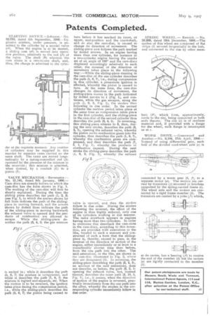
VALVE MECHANISM.-Reversator.-No. 21,145, dated 8th January, 1906.Cam discs are already known in which the cam-disc has the form shown in Fig. 1. The working of the cam-disc will first be shortly explained. During the time the sliding piece describes the path (1, 2, 3) (see Fig. 1, in which the arrows shown by full lines indicate the path of the slidingpiece in moving forward, and the arrows shown by dotted lines indicate the path of the sliding-piece in moving backward) the exhaust valve is opened and the products of combustion are allowed to escape. While the sliding-piece describes the path (3, 4, 5) the gas mixture
is sucked in ; while it describes the path (5, 6, 7) the mixture is compressed, and while it describes the path (7, 8, 1) the mixture is ingited and expands, etc. When the motion is to be reversed, the ignition takes place during the compression period, i.e., while the sliding-piece describes the path (5, (3, 7) the piston being caused to
turn before it has reached its inner, or upper, end-position and the crankshaft, and so also the cam-disc, is caused to change its direction of movement. The sliding-piece now follows the path marked by dotted arrows. In an engine having more than one cylinder, for instance in a two-cylinder, engine having the cranks set at an angle of 180° and the cam-discs displaced accordingly relatively to each other, the reversal of the direction of movement takes place in the following way I-While the sliding-piece running in the cam-disc of the one cylinder describes the path (5, 6, 7), i.e., during compression in this cylinder, a premature ignition is effected, whereby the piston is caused to turn. At the same time, the cam-disc changes its direction of movement, the sliding-piece moves in the path indicated by dotted arrows to 1 (Fig. 1), and continues, while the gas escapes, along the path (1, 9, 3, Fig. 1), the strokes then following in due order. In the second cylinder the suction period takes place at the same time as compression takes place in the first cylinder, and the sliding-piece in the cam-disc of the second cylinder thus describes the path (3, 4, 5). In reversing, this sliding-piece returns to 3, then, dur. ing the next stroke, describes the path (3, 2, I), opening the exhaust valve, whereby the piston sucks combustion gases into the cylinder, then describes the path (1, 8, 7), whereby the combustion gases are compressed, and then describes the path (7, 6, 1, Fig. 1), whereby the products of combustion expand. During the next stroke the sliding-piece describes the path (1, 9, 3, Fig. 1), whereby the exhaust valve is opened, and then the strokes follow in due order. During the strokes following the reversal, the effect of the engine is thus highly reduced, only one of its cylinders working in due manner. The same drawback appears in engines having more than two cylinders. In order to overcome this drawback the cam-slots in the cam-discs, according to this invention, are provided with extensions or the like, located in such a manner and constructed of such a form that the slidingpiece is, thereby, caused to pass, in the reversal of the direction of motion of the engine, either immediately or at least in a considerably shorter time than before, from the one path into the other. The said extensions, or the like, are shown in the cam-disc illustrated in Fig. 2, where they are designated (S). In reversing, the sliding-piece describing the path (3, 4, 5), on account of the said extensions, does not describe, as before, the path (3, 2, 1) opening the exhaust valve, but, instead thereof, describes the inner path (3, 10, 5, Fig. 1), i.e., it passes, when the direction of motion of the engine is reversed, practically immediately from the one path into the other, whereby the strokes in the corresponding cylinder immediately follow in due order, SPRING WHEEL. Kenrick.No. 28,989, dated 19th December, 1906.-The spokes of this wheel are composed of flat strips (b) secured tangentially to the hub, and connected to the rim by other mem bers (b1), which form, approximately, cords to the rim, being connected at both ends thereto. The rim (c) is of resilient material and, if provided with a flange for the wheel, such flange is interrupted as at e.
WORM DRIVE.Greenwood and Another.-No. 9,104, 17th April, 1908.Instead of using differential gear, each half of the divided road-wheel axle (4.) is connected by a worm gear (b, f), to a separate motor (a). The motors are carried by trunnions (j) mounted in brackets supported by the spring-carried frame (i). The wheel axle and the motors are connected by a rigid frame member (k). The trunnions are carried by a yoke (p) which, at its centre, has a tearing (.71) to receive the end of the member (k) but the motors (a) are rigidly connected to the member
(k)