


A Self-loading Vehicle
Page 58
If you've noticed an error in this article please click here to report it so we can fix it.
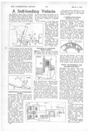
AVEHICLE fitted with a powered loading shovel is described in patent No. 649,935, which comes from Dempster Brothers Incorporated, Knoxville, Tennessee, U.S.A. The purpose is to use the same vehicle both for loading
• and the transport of soil and the like. The drawing shows the outfit with the shovel (1) reaching to the ground. The motion of the shovel is the resultant of two other motions, the swinging of the boom (2) about the pivot (3), and the longitudinal movement of the upright 'post (4). The latter can slide on guideways on the chassis, and is powered•by an hydraulic cylinder (5).
The boom is also worked hydraulically, its cylinder being shown at 6. By suitable manipulation, the shovel can pick up a load from the ground, and discharge it on to a sloping ramp (7) which leads to the inner body space. Alternatively, the shovel can be used to dig out material from the body and dump it on to the ground.
IMPROVEMENT IN WINDSCREEN WIPERS
THE windscreen wiper is only a small accessory, but one which can be vital at times, and it is rather regretful that, in some cases, it leaves much to be desired from the mechanical aspect. An attempt to improvb matters in this respect appears in patent No. 650,016, which comes from Vauxhall Motors, Ltd., Luton, Beds.
One of the chief defects of the ordinary type is that the motion accelerates towards, the ends of the stroke, and the sudden reversal. overstresses the flimsy parts and causes flicking and dithering of the blade. In A40
the present scheme, the motion of the arms is more nearly harmonic, that is, its velocity decreases towards the end of the stroke, resulting in a smoother reverse.
In the drawing, 1 is the wiper arm and 2 the reciprocating operating rod, which is driven by the • usual type of mechanism. The rod is coupled to the arm via the cross-over linkage shown, and the geometry is such that the fastest movement occurs over the middle of the stroke.
In this design it is impossible for the reciprocating link and crank arm to come into alignment to produce a toggle effect.
PROGRESS IN MAGNETIC BRAKE DESIGN W/HlEEL brakes operated by electro Vi' magnets form the subject of patent No. 649,964, from the Warner Electric Brake Manufacturing Company, South Beloit, Illinois, U.S.A. This particular design is aimed at the better dissipation of heat developed in use.
In the drawing, I is the rotary armature ring and 2 the stationary electromagnet. When the winding is energized, the two are attracted into frictional contact, the main rubbing surface being a ring (3) of friction material. The armature ring is not continuous, but is formed from a number of segmental pieces riveted on to a disc of thin metal (4). The rivets alone would not be very heat-conductive, and to improve this aspect, the segments are also copperbrazed to the disc.
A TORQUE-CONVERTER ONE-WAY CLUTCH
FROM the Borg-Warner Corporation, Chicago, Illinois, U.S.A., comes patent No. 649,586, in which is described a one-way clutch or freewheel of a typc suitable for building into a torque-converter.
In the drawing, an outer annulus (I) forms one member, and an inner race (2) the other. A cage member occupies the intervening space, and is slotted to receive a number of pawls (3) or "sprags" as they are called. Each sprag is loaded by a spring (4) and is of such a length that it can nearly reach the radial position. If the outer ring be moved to the left, it slides smoothly over the ends of the sprags, but movement to the right would be rigidly resisted by the jamming action of the sprags as they attempt to rock.
NOVEL TRANSMISSION FOR BA1TERY-ELECTRICS
PATENT NO. 649,577 comes from Hobbs Transmission, Ltd., 78, Russell Terrace, Leamington Spa, and shows a transmission layout intended for battery-electric vehicles. One of the features is that the driving motor is not permitted to reach a dangerously high speed if the load be removed.
Referring to the drawing, the shaded area (1) represents a revolving part attached to the driving motor. A twospeed epicyclic gear (2) can be locked solid by a clutch (3) to give direct drive, or used to reduce the speed by engagement of another clutch (4). Both clutches are hydraulically operated.
The hydraulic pressure is provided by a gear-pump (5) which is continuously driven. The driver's pedal moves a valve (6) in a tapered cylinder; in the off position the pump output is by-passed, but as the pedal is depressed, the restricting action gradually builds up a working pressure for actuating the clutches.
A control valve, shown generally at 7, is arranged so as to change to low gear automatically when the maximum permitted motor-torque is reached. The speedlimiting action arises from the presence of operating fluid in the clutch expander.
The device has applications in other spheres. such as for cranes.