


A NEW FOUR-WHEEL-DRIVE TRACTOR.
Page 26
If you've noticed an error in this article please click here to report it so we can fix it.
A Resume of Recently Published Patents
The difficulty which has hitherto always faced the designer of a four-wheel driven tractor has been the construction of the steering pivots, or their equivalent, through which the driving spindles of the front wheels had to be carried. Various methods of attaining this end have been suggested. Most of them, perhaps all of those which were worthy of notice, have had reference in these columns.
An American inventor, J. M. Kroyer, tackles the problem in a new -way. He
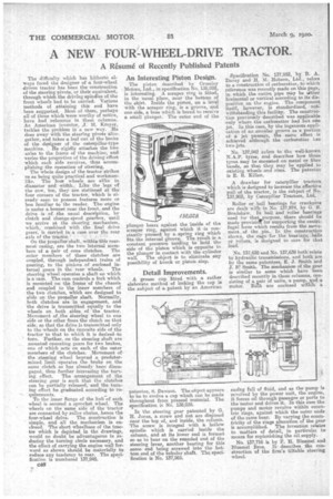
does away with the steeeing pivots alto gether, and takes a leaf out of the books of the designer of the caterpillar-type machine. He rigidly attaches the two axles to the frame of the machine, and varies the proportion of the driving effort which each side receives, thus accomplishing. the operation of steering, The whole design of the tractor strikes ns as being quite practical and workman like. The four wheels are alike in diameter and width. Like the legs of the cow, too, they are stationed at the four corners of the tractor, Which is al ready seen to possess features more or less familiar to the reader. The engine is under a bonnet near the front, and the drive is of the usual description, by clutch and change-speed gearbox, until we arrive at the steering mechanism, which; combined with the final drive gears, is carried in a ease over the rear axle of the trantor. • On the propeller shaft, within this rearmost casing, are the two internal mem bers of a pair of cone clutches. The outer members of these datches are coupled, through independent trains ef gearing, to the pinions of enclosed in ternal gears in the rear wheels. The steering wheel operates a shaft on which is a cam. The cam controls a fork which is mounted on the frame of the chassis and coupled to the inner members of the two clutches, which are designed to slide on the propeller shaft. Normally, both clutches are in engagement, and the drive is transmitted equally to the wheels. on both sides of the tractor. Movement of the steering wheel to one aide or the other frees the clutch on that side, so that the drive is transmitted only to the wheels on the opposite side of the
tractor to that to which it is desired 'to turn. Further, on the steering shaft are mounted operating gears for two brakes, one of which acts on each, of the outer members of the clutches. Movement of,
the steering wheel beyond a predetermined limit operates the brake on the same clutch as has already been disen gaged. thus further increasing the turn ing effect. The arrangement of the steering gear is such that the clutches can be partially released, and the turning effort be graduated according to requirements.
To the inner flange of the hub of each wheel is secured a sprocket wheel. The wheels on the same side of the tractor are connected by roller chains, hence the four-wheel drive. The construction is simple, and all the mechanism is en closed.The short wheelbase of the tractor which is depicted in the drawings,
-would no doubt be advantageous in re
ducing the turning circle necessary, and the effect of carrying the engine well for ward as shown should be materially to reduce any tendency to rear. The specification is numbered 137,945.
C46
An Interesting Piston Design.
The piston described by Crossley Motors, Ltd., in specification No. 138,028, is interesting. A scraper ring is fitted, in the usual place, near the bottom of the skirt. Inside the piston, on a level with the scraper ring, is a groove, and one side, a boss which is bored to receive sthall plunger. The outer end of the plunger beats against the inside of the scraper ring, against which it .is constantly pressed by a spring ring which fits. the internal groove. The result is a, constant pressure tending to hold the side of the piston which is opposite to the plunger in contact with the cylinder wall. The object is to eliminate any possibility of knock or piston slap.
Detail Improvements.
A grease cup fitted with a rather elaborate method of locking the cap is the subject of a patent by an American
patentee, S. Dawson. The object appears to be to evolve a cup which can be made throughout from pressed material. The specification is No. 138,035.
In the steering gear patented by G. H. Jones, a screw and nut are disposed near the top of, and inside, the column. The screw is integral with a hollow apiudle which is carried inside the column, and at its lower end is formed. BO as to bear on the rounded end of the steering lever, another bearing for this same end being screwed into the bottom end of the tubular shaft. The specification is No. 137,965. Specification No. 137,952, by B. A. Davey and H. M. Hobson, Ltd., refers to a construction of carburetter, to which reference was recently made on this page, in which the outlet pipe may be ther horizontal or vertical according to its disposition on the engine. The component itself, however, is standardized, notwithstanding this facility. The construction previously described was applicable only where the carburettor had but °fie jet. In this case, by the ingenious application of an annular groove as a portion of a jet passage' the same effect is achieved although the carburetter Las two jets.
• No. 137,942 refers to the well-known N.A.P. tyres, and describes how those tyres may be mounted on metal or fibre bands, so that they_ may be applied to existing wheels and rims. The patentee is E. B. Killen.
A drawbar for caterpillar tractors which is designed to increase the effective pull of the tractor, is the subject of No. 137,903, by Caterpillar Tractors, Ltd.
Roller or ball bearings for crankpins are dealt With in No. 137,874, by G. E. Bradshaw. In ball and roller bearings used for that ...purpose, there should be made provisiol! for supporting the centrifugal force which results from the move. anent of the pin. Li the construction shown, the cage for the bearings, balls or rollers, is designed to care for that load.
No. 137,638 and No. 137,639 both relate to hydraulic transmissions, and both are by the same patentees, E. J. Smith and J. IV:Smith. The Mechanism of the gear is similar to some which have been described recently in these columns, consisting of a pair of units, a pump, and a motor. Both are enclosed wiran a
easing full of fluid, and as the pump is revolved by the power unit, the engine, it forces oil through passages or ports to the motor and drives it. In this case the pumps and motor revolve within eccentric rings, against which the outer ends of the rams bear. By varying the eccentricity of the rings alteration or the gear is accomplished. The invention relates to matters of detail, in particulat to means for replenishing the oil supply.
No. 137,716 ia by F. H. Blnemel and 131nemel Bros. Itdescribes the conetruction of the firm's filial:de steering wheel.