


Contributions from Drivers and Mechanics.
Page 24
Page 25
If you've noticed an error in this article please click here to report it so we can fix it.
TEN SHILLINGS WEEKLY for the Best Communication Received, and One Penny a Line of ten words for any thing else published.
Drivers of commercial-motor vehic es and tra:tors, and mechanics and foremen of garages or shops, are invited to send shdrl contributions on any suVect which is likely to prove of interest to our readers. Work. shop tips and smart repairs ; long and successful runs ; interesting photographs : all are suitable subjects. Send a post-card, or a letter, or a sketch to us—no matter h w short, or how written, or how worded. We will " knock it into shape" and prepare sketches, where necessary, before publication. The absence of a sketch d es tint disqualify for a prize. When writing use one side of the paper only and men ion your employer's name as a guarant e of bona fides. Neither your own nor your employer's name mil be disclosed. Payment will be made immediately after publication. Address your letters to The I:ditor, THE CoirMERci.s1 lc, wiz, 7-15, Hosebery Avenue, London, E.G.
Some Engine-testing Rigs.
The sender of the following communication his been awarded a special bon .:s in addition to the 10s. prize this week.
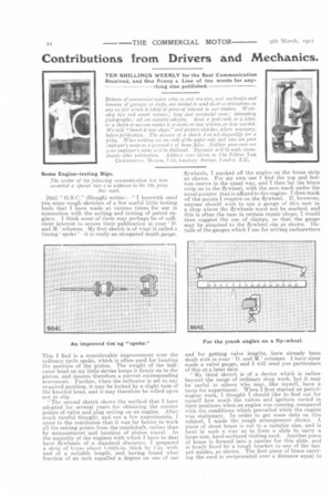
[845] " G.S.C." (Slough) writes :—" I herewith send you some rough sketches of a few useful little testing tools that I have made at various times for use in connection with the setting and -testing of petrol engines. I think some of them may perhaps be of sufficient interest to secure their publication in your 'I). and M.' columns. My first sketch is of what is called a
timing 'spoke is really an elongated depth gauge.
This I find is a considerable improvement over the ordinary cycle spoke, which is often used for locating the position of the piston. The weight of the indicator head on my little device keeps it firmly on to the piston, and insures therefore a correct corresponding movement. Further, when the indicator is set to any required position, it may be locked by a slight turn of the knurled head, and it may therefore be relied upon not to slip.
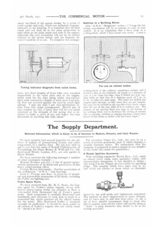
"The second sketch shows the method that I have adopted for several years for obtaining the correct points of valve and plug setting on an engine. After much careful thought, and not a few experiments, came to the conclusion that it was far better to work all the setting points from the crankshaft, rather than by measurement and location of piston travel. As the majority of the engines with which T have to deal have flywheels of a standard diameter, I prepared a strip of brass about 1-16th-in. thick by 1-in. wide and of a suitable length, and having found what fraction of an inch equalled a degree on one of our flywheels, I marked off the angles on the brass strip as shown. For my own use I find the top and bottom centre in the usual way, and I then lay the brass strip on to the flywheel, with the zero mark under the usual pointer that is affixed to the engine. I then mark off the points I require on the flywheel. If, however, anyone should wish to use a gauge of this sort in a shop where the flywheels must not be marked; and this is often the case in certain repair shops, I would then suggest the use of clamps, so that the gauge may be attached to the flywheel rim as shown. Details of the gauges which I use for setting carburetters
and for getting valve lengths, have already been dealt with in your ' D. and M.' columns. I have since made a valve gauge, and I will send you particulars of this at a later date.
"My third sketch is of a device which is rather beyond the range of ordinary shop work, but it may be useful to others who may, like myself, have a taste for experiment. When I first started on petrolengine work, I thought I should like to find out for myself how much the valves and igniters varied in their positions when an engine was running, compared with the conditions which prevailed while the engine was stationary. In order to get some data on this subject, I made the rough arrangement shown. A piece of sheet brass is cut to a suitable size, and is bent in such a way as to form a slide to carry a large-size, hard-surfaced visiting card. Another piece of brass is formed into a carrier for this slide, and is firmly fixed by a rough bracket to one of the tailpet guides, as shown. The first piece of brass carrying the card is reciprocated over a distance equal to
about. one-third of the piston stroke, by a series cf small cranks and rods, which are indicated diagrammatically in my drawing. It is essential that the first crank and rod shall be in the same proportion to each other as the main crank and rods of the engine, otherwise the card movement will not he in correct relation to the piston travel, and the diagram obtained would be of no use. To complete this arrange
ment, two short lengths of brass tube werc attached respectively to the valve stem and to the tappet, which were for the time being under observation. Each tube contained a length of hard stout lead pencil, that was pressed against the card by small light springs. I may say that I got very-satisfactory results from this rough arrangement. Should any of your readers try this, I fancy they will be very much surprised at the strength of the spring that is required to make a valve of any size follow this cam movement at anything like high speed." Addition to a Scribing Block.
,846J " R.W.S." (Brighouse) writes :—" I hope the following contribution will be of interest to sonic of your readers. It is an adaptation that I have made to a ,cribin;2:-bloch, which I have found very useful. I took a scribing-block of the ordinary round-base pattern and I scribed a line on its underside all round at a distance of in. or in. from the edge; then I drilled two +-in. tapping holes on that line at a distance apart of 1 in. or 1.; in. to take two steel pegs. The holes are drilled and tapped right through, so that when they are not wanted, the pegs can be screwed in the top side of the block, where they are out of the way while it is in ordinary use. The purpose of my placing these two pegs in the bottom of my scribing block was to facilitate the setting of certain jobs or, shaping, slotting or planing machines which have pliiueil T-slot. tables or tables with machined edges."