 1
1 2
2 3
3 4
4 5
5 6
6 7
7 8
8 9
9 10
10 11
11 12
12 13
13 14
14 15
15 16
16 17
17 18
18 19
19 20
20 21
21 22
22 23
23 24
24 25
25 26
26 27
27 28
28 29
29 30
30 31
31 32
32 33
33 34
34 35
35 36
36 37
37 38
38 39
39 40
40 41
41 42
42 43
43 44
44 45
45 46
46 47
47 48
48 49
49 50
50 51
51 52
52 53
53 54
54 55
55 56
56 57
57 58
58 59
59 60
60 61
61 62
62 63
63 64
64 65
65 66
66 67
67 68
68 69
69 70
70 71
71 72
72 73
73 74
74 75
75 76
76 77
77 78
78 79
79 80
80 81
81 82
82 83
83 84
84 85
85 86
86 87
87 88
88 89
89 90
90 91
91 92
92 93
93 94
94 95
95 96
96 97
97 98
98 99
99 100
100 101
101 102
102 103
103 104
104 105
105 106
106 107
107 108
108 109
109 110
110 111
111 112
112 113
113 114
114 115
115 116
116 117
117 118
118 119
119 120
120 121
121 122
122 123
123 124
124 125
125 126
126 127
127 128
128 129
129 130
130 131
131 132
132 133
133 134
134 135
135 136
136 137
137 138
138 139
139 140
140 141
141 142
142 143
143 144
144 145
145 146
146 147
147 148
148 Types of gearboxes
Page 94
If you've noticed an error in this article please click here to report it so we can fix it.
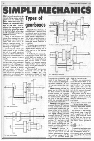
Figureti-liOws the layout of this type of box. The drive from the clutch is taken by the clutch shaft to the small constant mesh wheel, which is integral with it. This wheel is permanently in mesh with the large constant mesh gear, which is secured to the layshaft.
Three other gears are secured to the layshaft which is supported at each end by ball or roller bearings in the gearbox 'housing.
A third shaft, the mainshaft, is arranged in line with the clutch shaft and parallel to the layshaft. It is supported at its rear end by a ball or roller bearing in the gearbox housing and at its front end by a spigot which fits into a bushed hole in the clutch shaft.
The mainshaft carries two members "A" and B'' on splines (Figure 1). This arrangement allows "A" and —13" to be slid along the -mainshaft by the selector forks which fit into the grooves "C" and "D" shown on the diagram. Because of the splines, "A" and "B" cannot revolve on the main shaft.
Figure 1 shows first gear engaged and it will be seen that the drive from the clutch shaft travels through the constant mesh gear and the layshaft to the bottom gears, which take the drive to the main shaft to which the universal joint and propeller shaft are coupled.
Figure 2 shows second gear engaged. Member "B" has now moved forward so that the smaller wheel engages with the bigger wheel on the layshaft, thus obtaining a higher ber ratio Figure 3 shows third gear engaged. Member "B" has now moved back so that it is not -engaged with any gear, and member "A" has been moved back so that it engages with the third speed gearwheel on the layshaft, providing a further increase in the gear ratio.
In Figure 4, member "A" has moved forward so that it is clear of any wheel on the layshaft but so that the dogs on its front face engage with the dogs on the constant mesh wheel on the clutch shaft.
The drive now comes directl) from the clutch shaft to thE mainshaft with no intermediatc gear involved. The constan mesh gears still. turn th( layshaft, but the shaft is idlinc only. In this position, of course the gearbox is in top gear.
Gear ratios may be easil) found, if the number of teeth or each gear wheel is known, 13) using the simple formula Gear ratio= Product of the number of teeth on each driven wheel Product of the number of teeth on the driving wheels
For example, if the constan. mesh pinions have 20 and 3F. teeth respectively, and thE second gear mainshaft pinior has 30 teeth and the meshinc layshaft pinion 25 teeth, thE gear ratio in second gear woulc be
There would be a further geai reduction in the rear axle, probably somewhere about 5 1, which would give an overal gear ratio of 10.5:1 in seconc gear.