


A NEW Three roll
Page 46
Page 47
If you've noticed an error in this article please click here to report it so we can fix it.
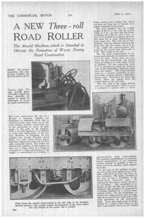
ROAD ROLLER
TN road construction the use of a _troller is essential, whether for feunclationor surfacing work, and in cannectiontwith such work one of the .mot comthon troubles experienced lies Ia.. the generation of waves at right angles to the path of the machine. With n two-roll appliance it is difficult to avoid sncli deformation of the surface, therefore, in designing its new machine the Arnold Waveless Road Roller Co., Ltd., Brick House Farm, Kelvedon, Essex, has made use of three rolls, unequally spaced. The centre one obviates the tendency of the machine to ride over a ridge ; thus, if a hump be encountered a large proportion of the weight is comentrated on levelling it.
When passing over a hollow the centre roll does not drop into it because it is rigidly connected to the frame.
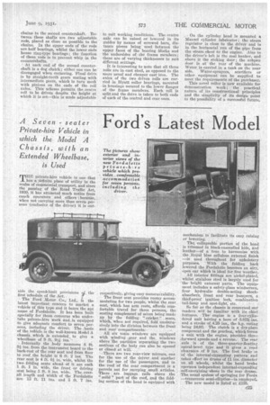
The new machine has an overall length of 16 ft. 4 ins, and an overall width of 7 ft. ; on each side the frame overhangs the rolls by only 7 ins., so that it is possible to compress the surface close up to such obstructions as lamp posts, etc. The rolls are of 4 ft. diameter, and the distance between the front -one arid the centre one is 6 ft. 7 ins., whilst the centre-to-centre distance of the second and third rollsis 5 ft. The weight is 14 tons.
For the main longitudinals of the frame steel channels are employed ; these are 1 ft. deep. From them run supports for the forecarriage, the lateral apron of which is in boiler plate riveted in position. To the supporting members in question are fixed the forward ends of the longitudinal channels which carry the engine. The front-roll fork turns in a bearing consisting of fin. steel balls working against a phosphorbronze race. Steering is by worm and wheel; there are chains from The lateral shaft to the roll fork.
The rear ends of the engine bearers rest on a cross-membep, which in turn is anchored to spacers above a awn.
channel-section main cross-member. Two separate longitudinals run from the lateral engine-bearer to an L-section member carried on uprights at the extreme rear of the machine ; these support the boiler.
In the case...of the machine in question the power unit employed is a Yorkshiac, with 4A-in. by 8-in. and 71-in. by 8-in. cylinders. The boiler, mounted at the rear, is also a Yorkshire, Of the double-ended locomotive type. We understand that future models will have an oil engine. The crankshaft is extended on the off side and carries the flywheel; this extension is supported by a bearing mounted on a special longitudinal girder. On the crankshaft extension is a sliding pinion with 18 teeth ; this can be moved into mesh with a 120tooth gearwheel on the first-Motion shaft. From this shaft power is transmitted by a single roller chain to the first countershaft, thence by two duplex
chains to the second countershaft. Between these shafts are two adjustable rode, placed as close as possible to the chains. In the upper ends of the rods are half bearings, whilst the lower ends house ring-type bearings ; the function of these rods is to prevent whip in the countershafts.
At each end of the second countershaft is a dog clutch; either one can be disengaged when cornering. Final drive is by straight-tooth gears mating with intermediate gears, which in turn mesh with pinions on the ends of the roll axles. This scheme permits the centre roll to be driven despite the height at which it is set—this is made adjustable to suit working Conditions. The centre axle can be raised or lowered in its guides by means of screwed bars, distance pieces being, used between the upper faces of the bearing blocks and the undersides of the frame members ; these are of varying thicknesses to suit different settIngs.
It is interesting to note that all three rolls arc in cast steel, as opposed to the more usual and cheaper cast iron. The axles of the two driven rolls are carried in Hyatt roller bearings, mounted in housings secured to the lower flanges of the frame members. Each roll is split and the drive is taken to both ends of 'each of the central and rear ones. On the cylinder bead is mounted a Menzel cylinder lubricator ; the steam regulator is close to the driver and is in the horizontal ,run of the pipe from the steam chest to the engine. Also to the driver's left is the coal bunker, and above it the stoking door ; the ashpan door is at the rear of the machine. Water is carried in a tank on the near side. Water-sprayers, scarifiers or other equipment can be supplied to meet the requirements. of the purchaser.
This novel roller is now available for demonstration work ; the practical nature of its constructional principles and the simplicity of its design point to the possibility of a successful future.