


Patents Completed.
Page 22
If you've noticed an error in this article please click here to report it so we can fix it.
Complete specifications of the following patents will be sent to any address in the United Kingdom upon receipt of eightpence per copy at the Sales Branch, Patent Office, Holborn, W.C.
MOTOR LAWN MOWERS.—Ransomes, Sims and Jefferies. Ltd.. and A. W. Bromley.—No, 17,533, dated 28th July, 1909.—Thi5 invention relates to a clutch device, whereby the cutting cylin ders can be brought into or out of operation as desired. The driving shaft has a stationary and a slidable cone member mounted on it, and these are adapted to engage a similarly-coned internal portion of the 'sprocket. The cone members on the driving shaftare normally pressed apart by means of springs. A hand wheel is mounted on the end. cif the driving shaft, and this is adapted to push the slidable cone into contact with the sprocket.
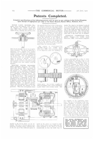
ELECTRIC POWER TRANSMISSION SYSTEM.—Durtuall.—No. 6,758, dated 20th March, 1909,—According to this invention, the engine shaft carries the magnet of a polyphase alternating generator and also the primary element of a polyphase induction motor, the secondary element of which is mounted on the driven shaft. The armature of the generator is supported on the side members of the frame of the vehicle, and it supplies current through suitable controlling switches and slip rings to the induction motor. A separate exciter, driven from the engine shaft, is also provided for exciting the magnet of the generator. 'With this arrangement three
speeds of the driven shaft can be obtained. The first or lowest speed is obtained by creating a rotary magnetic flux in the air cap of the induction motor in
the opposite direction to that of the primary element carried by the engine shaft so that the driven shaft will be dragged or pulled round at a less speed than the driving shaft. The second speed is obtained by means of a magnetic friction clutch which couples the driving and driven shaft so that a direct drive is obtained. The third or top speed is obtained by altering the direction of -the current so that the rotary magnetic flux will rotate in the same direction as the primary element of the induction motor and thus accelerate the driven shaft up to a greater speed than the driving shaft.
The cutting of INVOLUTE GE AHS.—Poppe.—No. 14,793, dated 24th June, Mg.—This invention relatcs to an improved totter for finishing in volute gears. An involute roughly-cut wheel is meshed with a cutter resembling a gear wheel with involute teeth. The teeth on the cutter are formed so that their corners form cutting edges and the outer periphery of the cutter is ground eccentrically so that the teeth vary in depth. The wheel to be finished is placed in a recessed bearing and is gradually advanced towards the cutter until one side of the teeth has been reduced to its proper size and form. The wheel is then turned round in the carrier, so that the other side of the teeth may he finished.
INTERNAL COMBUSTION TURBINE.— Morgan.— No. 14,559, dated 22nd June, 1909.—This turbine comprises
a drum surrounded by a ring or outer casing which has inclined vanes on its inner periphery and cooling ribs on its outer periphery. Within the drum, a cylindrical chamber is formed, and in this is mounted a piston which is reciprocated by means of an eccentric carried by a concentrically-arranged shaft. This cylinder and piston perform the function of a double-acting air pump which forces air, past non-return valves in the ends of the cylinder, to the combustion chambers. The air, in travelling to the combustion chamber, is caused to mix with fuel, which latter becomes vaporized. The mixture thus obtained is ignited in the first instance by means of a sparking plug, with the result that the bigh-pressurc gases act upon the vanes and cause the drum to rotate. The exhaust takes place through slots in the rim of thedrum. The succeeding charges are ignited by the heat of the first explosion.