


Patents Completed.
Page 26
If you've noticed an error in this article please click here to report it so we can fix it.
Locking Selector-rods. Improving Magnetos. A Simple Spring Drive.
GEERUDER STOEWER, NO. 58 of 1914, dated under International Convention, 18th October, 1913.—This specification describes a simple form of locking device for the control rods of a motor vehicle. The lock consists of a plate pivoted beside the rods, and slotted to receive studs or projections on the latter.
A lateral slot is formed in the plate, concentric with the pivot pin, and a series of branch slots extend out from it. In the normal position all the studs on the control rods lie in the lateral slot, and any rod can be moved longitudinally, causing its stud to move into one of the branch slots.
These are inclined to one another se that when a stud is moved into one of them it either holds the locking plate against movement or swings it to one side or the other and then locks it, so that the studs on the other control rods cannot enter their respective branch slots, and the rods are therefore locked.
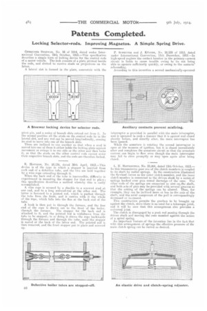
R.. HousTosi, No. 10,136, dated 30th April, 1913.—This device is of the type in which a stopper is inserted from each end of a defective tube, and the two are held together by a wire rope extendiug through it.
When the. back end of the tube is inaccessible, difficulty is experienced in mounting the stopper for that end in place; this specification describes a method whereby this is easily Recompliehed.
A. wire rope is secured by a shackle to a screwed stud at one end, and to a long screwed-rod at the other end. The latter is fastened to a jointed rod, which is pushed through the tube front the front, and it carries with it the whole of the rope, which falls into the flue at the back end of the tube.
A hook is then put in through the furnace, and the free end of the rope is drawn out to the. front of the boiler,
through the furnace. The stopper for the back end is attached to it, and the pointed rod is withdrawn from the tube to be stopped; in so doing it draws the rope backwards through the furnace and through the tube, until the stopper is seated at the hack of the latter end. The pointed rod is then removed, and the front, stopper put in place and screwed up.
P. ScHrtorEn and J. IittiTER, No. 28,535 of 191.3, dated under International Convention, 11th December, 1912.—In high-speed engines the contact breaker in the primary-current circuit is liable to cause trouble owing to its not being able to operate sufficiently quickly, or owing to the oontacts' rebounding. According to this invention a second mechanically-operated interrupter is provided in parallel with the main interrupter, and is operated in such a manner that it is opened and closed shortly before, and directly after, the main interrupter has been opened. iVhile the armature is rotating the second interrupter is open at. the moment of ignition, but it is closed immediately after and completes the armature circuit so that the armature current can begin to flow even though the main interrupter may fail to close promptly or may open again after being closed.
L. II. HortesrIELD, No. 23,064, dated 13th October, 1913.— In this transmission gear one of the clutch members is coupled to its shaft by radial springs. In the construction illustrated the flywheel serves as the, outer clutch-member, and the inner clutch-member is connected to the driven shaAt by a series of springs hooked over pins round the the cone. The other ends of the springs are connected DO oins ouithe shaft, and both &As of pins may be provided with several grooves so that the netting of the springs can be altered. Thus, for example, they can be inclined more or less to the axis of the shaft., and the axial component of the pull is correspondingly decreased or increased.
This construction permits the gearbox to be brought up against the clutch, since there is no need for a telescopic joint, and it will be seen that this arrangement also provides a universal joint.
The clutch is disengaged by a push rod passing through the driven shaft and moving the cone member against the action of a spiral spring. An important feature of the invention lies in the fact that with this arrangement of springs the elective pressure of tilt main (hit( h spring can be varied as desired.