


The Steward Tubeless Boiler.
Page 3
Page 4
If you've noticed an error in this article please click here to report it so we can fix it.
Some Interesting Figures and Tests with a New Form of Rapid Steam Generator
In spite of the many attempts, on the part of petrol-wagon designers, to produce machines that will compare favourably with steam wagons in point of economy and reliability, the latter class of road vehicle continues to hold its own for loads of five tons and upwards. One of the most vital and troublesome items in the construction of a steam wagon is the boiler : sooner or later, the tubes will leak and give trouble ; and the water level must be most carefully watched and the contents of the boiler kept at a nearly constant level. The flash, or semi-flash, generator is free of these disadvantages to a certain extent, but it is far less efficient in many respects. Superheating of the steam has been practised, with more or less success, by numerous steam-wagon and tractor builders during recent years. Amongst the first engineers to test the economy of superheating steam was the late Mr. Penn (of J. Penn and Sons) who, in 1857, fitted superheating apparatus into the s.s. " Valetta," the immediate result of which was a saving of 20 per cent, in the consumption Of fuel. The pressure of the steam operated upon by Mr. Penn and others about that time, when so much economy was obtained by superheating-, was only about 201b. per square inch above abmospheric pressure or 351b. absolute. This corresponds to a temperature of 259 degrees Fahrenheit, so that the steam might have had a considerable degree of superheat imparted to it before the limiting temperature for practical working (360 degrees Fahr.) was attained. When steam becomes too hot, the lubricants of the cylinder and slide valves become burnt up to such an extent that abrasion of the valve faces takes place. With steam at a temperature above 400 degrees Fahr., proper lubrication and packing is a difficult matter. As steam pressures increased with the advancing methods of en'gine and boiler construction, this trouble became more pronounced, and the practice of superheating fell into disuse. With steam at J5olh. per square inch, the temperature would be 166 degrees Fahr. ; it will, therefore, be seen that only a small degree of superheat could be imparted to the steam, if intended for use on engines not specially designed for it. • Great advances have been made recently in engines designed for running on
superheated steam, and a need is now fell. for a rapid steam generator, that will produce a constant supply of perfectly. dry steam, with a given degree of superheat, and with a good reserve of steam to meet the sudden and excessive demands which are occasionally made upon it when used on a steam wagon or tractor. Mr. G. R. Steward, 111.I.Mech.E.., of 28, Victoria Street, Westminster, claims to have invented a boiler which meets all the conditions laid down by designers and builders of such vehicles. From our own careful observation of his boiler under test, we are of opinion that the claim n is no idle boast. The inventor is an engineer who has had many years of experience with steam engines and boilers in all the European navies; he was the guarantee engineer to J. Penn and Sons; he was associated with the late Sir Edward Reed (Naval Constructor); and he was head of the firm of Steward and Latham, of Blackwall.
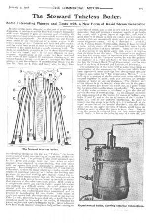
The construction of the boiler will be understood from an examination of the accompanying illustrations which have been reproduced from drawings and photographs specially prepared and taken for " THE COMMERCIAL MOTOR." It is built up of a number of double-conical steel tubes which are secured together in pairs; each pair encloses an annular column of water of varying thickness. The thickest part of the column is at the bottom, where the heat is the greatest, and thinnest just below the water line, aL a point where the hot gases have cooled down considerably. This tapering off of the water columns is calculated to give the best results in the way of steam raising. All the annular chambers are inter-connected at the bottom by means of hollow, stay bolts (E and F), and at the top by means of the " header ' tubes (G), seen in our sectional illustration. In order to ensure that the steam is perfectly dry, it is collected, at the upper extremities of the annular chambers, into the coiled tubes (M), in the upper surfaces of which, small holes are drilled in order to allow the steam to enter them. Step by step, the steam is collected from the four steam vessels, until, finally, it leaves the boiler by Way of a tube (H) and
superheater coil (1), to the regulating valve (K). From this point, the steam pipe (L) may be taken in any direction to the engine. Water is pumped into the boiler near the bottom, and, by way of the hollow, stay bolts, it rises to an equal height in each of the four chambers. In order to assist in maintaining a more constant water level than is possible with vessels having so low a capacity, an annular saddle (A) is added to the outer wall of the outermost vessel; a series of holes (B) permits steam to enter and replace the water which leaves the chamber (A) by way of the bottom set of holes (C). It will be noticed that there is a tube (D) within this water saddle, and that it is connected with the main, superheated-steam, supply pipe; its object is, that the hot gaseous steam may escape from the tube (D) by way of the small holes which are drilled in the upper side, and, by rising through the water, raise its temperature up to the boiling point. When one considers that the water and the steam within the saddle (A) are at the same pressure as the steam which is supposed to enter, by way of the tube (D), the usefulness of this tube is rather problematical ; still, highly superheated steam has so many peculiar properties that we should not be surprised if the inventor's ideas proved to be correct. As far as we can see, the only convincing way of showing the usefulness of the fitting would be the provision of a large, glass-covered " spy-hole " in the wall of the saddle so that the rising, gaseous steam could be seen.
This boiler may, when a sudden demand is made upon it for an extra quantity of steam, be used as a semi-flash generator. For this purpose, water is pumped in through the tube (0), and from thence it is distributed to the coils (N); through a number of small holes, the numerous jets of water strike the inner sides of the second and third boiler vessels, and they are instantly " flashed "into steam.
The shell of each wall, of each vessel, is made up of two halves which are flanged and riveted, or 'bolted, together. One of our illustrations shows two of these pieces, which are of cast steel. It will be seen that the joint is a vertical one and the vertical masses of metal in the flanges will be valuable " beat-stores " to be called upon during momentary failures of the furnace; it has been found that so much heat is stored within these flanges that the inventor has been induced to add vertical webs, as will be seen in the illustration below.
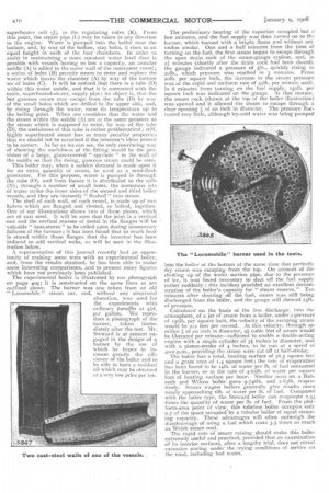
A representative of this journal recently had an opportunity of making some tests with an experimental boiler, and, from the results obtained, he has been able to make some interesting comparisons, and to present many figures which have not previously been published.
The experimental boiler is illustrated by our photograph on page 409; it is constructed on the same lines as are outlined above. The burner was one taken from an old " Locornobile " steam car, and, without any structural alteration, was used for the experiments with ordinary paraffin at +id. per gallon. We reproduce a photograph of the burner, taken immediately after the test. Mr. Steward is at present engaged in the design of a burner by the use of which he hopes to increase greatly the efficiency of the boiler and to be able to burn a residual on which may be obtained at a very low price per ton. The preliminary heating of the vaporiser occupied but a few minutes, and the fuel supply was then turned on to the burner, which burned with a bright flame and without any undue smoke. One and a half minutes from the time of turning on the fuel, the first steam began to escape through the open drain cock of the steam-gauge syphon, and, in 2.+ minutes (shortly after the drain cock had been closed), the gauge indicated a pressure of go., quickly rising to 201b., which pressure Was reached in 3 minutes. From 211b. per square inch, the increase in the steam pressure was at the rapid and uniform rate of 431b. per minute until, in 6 minutes from turning on the fuel supply, isolb. per square inch was indicated on the gauge. At that instant, the steam cock (shown at the top of the boiler illustration) was opened and it allowed the steam to escape through a clear opening ;A of an inch in diameter. The pressure fluctuated very little, although icy-cold water was being pumped
into the boiler at the bottom at the same time that perfectly dry steam was escaping from the top. On account of the choking up of the water suction pipe, due to the presence of ice, it was found necessary to shut off the fuel supply rather suddenly : this incident provided an excellent demonstration of the boiler's capacity for " steam reserve." Ten minutes after shutting off the fuel, steam was still being discharged from the boiler, and the gauge still showed 251bof pressure.
Calculated on the basis of the free discharge, into the atmosphere, of a jet of steam from a boiler, under a pressure of 15o1b. per square inch, the velocity of the escaping steam would be 212 feet per second. At this velocity, through an orifice g of an inch in diameter, 91 cubic feet of steam would be liberated per minute—sufficient to enable a double-acting engine with a single cylinder of 3i inches in diameter, and with a piston-stroke of 4 inches, to be run at a speed of 400r.p.m., providing the steam were cut off at half-stroke.
The boiler has a total, heating surface of 36.5 square feet and a grate area of 1.4 square feet ; the rate of evaporation has been found to be 141b. of water per lb. of fuel consumed in the burner, or at the rate of 4.631b. of water per square foot of heating surface per hour. Similar tests on a Bab-. cock and Wilcox boiler gave 9.746lb. and 2.831b. respectively. Steam wagon boilers generally give results more nearly approaching 6Ib. of water per lb. of fuel. Compared with the latter type, the Steward boiler can evaporate 2.33 times the quantity of water per lb. of fuel. From the platform-area point of view, this tubeless boiler occupies only 0,7 of the space occupied by a tubular boiler of equal steaming capacity. These advantages will often outweigh the disadvantage of using a fuel which costs 3.5 times as much as Welsh steam coal.
The rapid rate of steam raising should make this boiler extremely useful and practical, provided that an examination of its interior surfaces, after a lengthy trial, does not reveal excessive scaling under the trying conditions of service on the road, including bad water.