


An Infinitely Variable Gear
Page 60
If you've noticed an error in this article please click here to report it so we can fix it.
A IVsur'a of Recently Published Patent Specifications
A N interesting invention is described in patent No. 11363,985, by S. M. L. Hall, 34b, CIanricarde Gardens, London, W,2, and E. G. E. Beaumont. The gear is called "A variable-speed mechanism and power-transmission gear." The title and description are, however, not very clear on one point. That with such a gear speed can be varied, and that power can he transmitted, we have no doubt, The point we should like made clear it whether the power ratio of driver and driven can be varied, as this has proved to be the difficulty with which most inventors have been met.
The present invention consists of a driving shaft (A) to which is attached a flywheel (F) and a stud-carrier (B), all of which rotate as one. Freely mounted upon the shaft is a sleeve which carries at its right end a pinion (C), and at its other end two eccentrics (E). Also. freely mounted on the shaft is a bell-shaped member (D), which has internal teeth engaging with the planet pinions, whilst at its other end it is provided with a flange (H), which may be connected to a rear axle or other part to be driven.
The eccentrics have straps which ternainate in weights (W)• These weights are connected by links to studs (M) which aroject from the flywheel.
The action of the device would appear to be as follows :—When the driving shaft is rotated it carries with it the flywheel, the weights and the carrier (B). Should there be no resistance to the driven portion, all would rotate together, but if resistance be applied to the drum D it would be retarded or held still. This would cause the planetary pinions to rotate on their axes, thus setting up a rapid rotation of the eccentrics and so causing the weights to move at first towards, and then away from the centre of the flywheel as they rotate with it.
Centrifugal, force would help them on their outward movement, but would resist. them as they move towards the centre, causing a'jerk to be exerted on the driven member. The frequency with which these jerks occur as the speed of the driving shaft increases and the consequent increase of resistance due to centrifugal force, would appear, to be the means relied upon to transmit power to the driven member.
Double Springs for Tractors.
THE names of Karrier Motors, Ltd., It. F. Clayton, R. Dean-Averns, and P. Meek appear in specification No. , 864,355, which would appear to apply mainly to the springing of three-wheeled tractors of the type in which part of the load of the drawn vehicle rests on the tractor, thus causing a difficulty when running without the trailer.
The object of the present invention is to provide a double set of springs, the stronger of which only come into action when a trailer is bearing on the tractor. The upper springs are those that are at all times in operation, the slotted links shown in broken lines only coming into action, as shown, when the extra load is being carried.
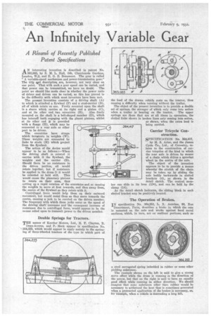
Carrier Tricycle Construction.
SPECIFICATION No. 364,417, . by M. S. Arter, and the James Cycle to., Ltd., of Coventry, relates to the construction of carrier tricycles of the kind in which the rear axle is driven by means of a chain which drives a sprocket wheel in the centre of the axle.
The object of the invention appears to be to provide a means whereby the stretch of the chain may be taken up by sliding the axle bodily backwards in slotted brackets (4), as shown in the detail sketch. The central memboss (13e), and can be held by the ber can slide in clamp (14): As the detail sketch indicates, the sliding block in each slotted bracket may be positively located.
The Operation of Brakes.
IN specification No. 364,253, L. X. Antelme, 80, Rue Damrknont, Paris, describes a brake in which the cam is mounted on the axle and works against hard metal surfaces, which, in turn, act on resilient portions, such as a steel corrugated spring imbedded in rubber or some other yielding substance. The example shown on the left is said to give a strong servo effect while the drum is running in the direction of the arrow, but that an the right is said to have an equally good effect while running in either direction. We should imagine that some substance other than rubber would be necessary to withstand the heat that is sometimes generated when a protracted application of the brakes is necessary, as, for example, when a vehicle is descending a long hill.