


Tool for Removing Large Tyres
Page 60
If you've noticed an error in this article please click here to report it so we can fix it.
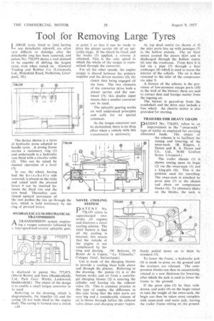
ARGE tyres, fitted to rims having one detachable sidewalt, are often very difficult to dislodge after the detachable ring has been removed, and patent No. 778,079 shows a tool claimed to be capable of shifting the largest tyres, even when rusted on. (General Trading and Rubber Co. (Liverpool), Ltd., Wakefield Road, Netherton, Liverpool, 10.) The device shown is a form of hydraulic press adapted to handle tyres. A strong frame carries a stationary ring (I) and underneath is a hydraulic ram fitted with a circular table (2). This can be raised by manual operation of a lever
In use, the wheel, having had the detachable side removed, is placed on the table and raised until the pivoted levers 4 can be inserted between the fixed rim and the tyre bead. Thereafter, continued upward movement of the ram pushes the rim up through the tyre, which is held stationary by the ring of pivoted levers.
HYDRAULIC-CUM-MECHANICAL TRANSMISSION
A TRANSMISSION system employing a torque converter followed by a four-speed-and-reverse epicyclic gear,
is disclosed in patent No. 777,073. (David Brown and Sons (Huddersfield), Ltd., Park Gear Works, Lockwood, Huddersfield.) The object of the design is to enable a small torque converter to be used.
Referring to the drawing, which is diagrammatic, the impeller (1) and the casing (2) are both fixed to the engine shaft. The casing is formed into a clutch 534
at point 3 so that it can be made to drive the planet carrier (4) of an epicyclic stage. If the clutch be freed. and the brake (5) applied, a reverse is obtained. This, is the only speed in which the whole of the torque is transmitted through the converter.
For all the other speeds, the engine torque is shared between the primary impeller and the driven member (6), the clutch then being engaged all the time. The two elements of the converter drive both a planet carrier and the sunwheel (7); this double input means that a smaller converter can be used.
The epicyclic gearing works on well understood principles and calls for no special comment.
As the torque converter can be declutched, there is no drag effect when a vehicle with this transmission is stationary.
NOVEL COOLING SYSTEM DATENT No. I 778,195 refers to supercharged twostroke oil engines and discloses a novel cooling scheme, The chief feature is that all the cooling is internal; this means that the outside of the engine is not complicated by fin ning and ducting. (W. Behrens, 39 Route de la Capite, 'La Villanelle," Cologny Genf, Switzerland.)
Use is made of the charging blower to provide a cooling blast both above and through the pistons. Referring to the drawing, the piston (1) is at the bottom stroke and air from a centrifugal charging blower (2) is entering the cylinder and leaving via the exhaust valve (3). This is common practice in this type of engine, the difference in this case being that the inlet ports are .very big and a considerable volume of air is blown through before the exhaust valve closes and charging proper begins.
At top dead centre (as shown at 4) the inlet ports line up with passages (5) in the hollow pistons. The air blast enters around the piston skirt and is discharged through the hollow centre (6) into the crankcase. From here it is led via a pipe (7) through a heat exchanger (8) which is used to warm the interior of the vehicle. The air is then returned to the inlet of the compressor via pipe 9.
A feature of the scheme is the provision of low-pressure escape ports (10) in the wall of -the blower; these are said to extract dust and foreign matter from the ingoing air.
The blower is geared-up from the crankshaft and the drive may include a free wheel. An electric motor is also provided for starting.
TRAILERS FOR HEAVY LOADS
PATENT No. 778,055, refers to an 1 improvement in the " swan-neck " type of trailer as employed for carrying abnormal loads. The object of the scheme is to facilitate the raising and lowering of the swan-neck. (R. Rippon. J. Dyson and R. A. Dyson and Co., Ltd., 76-80 Grafton Street, Liverpool.)
The trailer chassis 0) is shown resting upon its bogie (2) via the swan-neck (3) and a king-pin (4). This is the position used for travelling. The swan-neck is attached by pivot pins (5) to the chassis and abuts on compression blocks (6). To eliminateshake on the blocks, the neck is firmly pulled down on to them by strainers (7). • To lower the frame, a hydraulic jack (8) is made to press on the ground and the strainers are released. The compression blocks can then be eccentrically rotated to a new thickness for lowering, after which the jack is used to lower the frame to the ground.
If the pivot pins (5) be then withdrawn, and jacks (9) on the bogie raised to take the weight of the swan-neck, the bogie can then be taken away complete with swan-neck and main jack, leaving the trailer frame resting on the ground.