


CONVERTING VEHICLES F M FOUR WHEELS TO SIX.
Page 50
Page 51
Page 52
If you've noticed an error in this article please click here to report it so we can fix it.
How Existing Vehicles May be Converted ti and,at the Same Time May "ye a 40 per cent. Increase in Load Capacity Relieved of Much Road Shock.
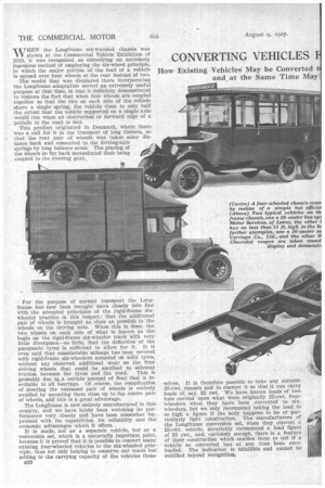
WHEN the Longframe six-wneeled chassis was shown at the Commercial Vehicle Exhibition of 11423, it was recognized as embodying an extremely ingenious method of employing the six-wheel principle, in which the major portion of the load of a vehicle is spread over four wheels at the rear instead of two.
The model that was displayed there incorporating the Longframe adaptation served an extremely useful purpose at that time, in that it definitely demonstrated to visitors the fact that when four wheels are coupled together so that the two on each side of the vehicle share a single spring, the vehicle rises to only half the extent that the vehicle supported on a single axle would rise when an obstruction or forward edge of a pothole in the road is met.
This product originated in Denmark, where there was a call for it in the transport of long timbers, so that the rear pair of wheels was taken some distance back and connected to the driving-axle springs by long balance arms. The placing of the wheels so far back necessitated their being coupled to the steering gear.
For the purpose of normal transport the Longframe has: now been brought more closely into line with the accepted principles of the rigid-frame sixwheeler practice in this respect : that the additional' pair of wheels is brought as close as possible to the wheels on the driving axle. When this is done, the two wheels on each side of what is known as the bogie on the rigid-frame six-wheeler track with very little divergence—so little, that the deflection of the pneumatic tyres is sufficient to allow for it. It is even said that considerable mileage has been covered with rigid-frame six-wheelers mounted on solid tyres, without any observed additional wear on the four driving wheels that could be ascribed to sideway friction between the tyres and the road. This is probably due to a certain amount of float that is inevitable in all bearings. Of course, the complication of steering the rearmost pair of wheels is entirely avoided by mounting them close up to the centre pair of wheels, and this is a great advantage.
The Longframe is now entirely manufactured in this country, and we have lately been watching its performance very closely and have been somewhat impressed with its capabilities, its reliability and the economic advantages which it offers.
It is made, not as a separate vehicle, but as a conversion set, which is a materially important point, because it is proved that it is possible to convert many existing four-wheeled vehicles to the six-wheeled principle, thus not only helping to conserve our roads but adding to the carrying capacity of the vehicles them B32
selves. It is therefore possible to take any suitable 25-cwt. chassis and to convert it so that it can carry loads of, say, 35 cwt. We have known loads of two tons carried upon what were originally 25-cwt. fourwheelers when they have been converted to sixwheelers, but we only recommend taking the load to so high a figure if the body happens to be of particularly light construction. The manufacturers of the .Longframe conversion set, When they convert a 25-cwt. vehicle, invariably recommend a load figure of 35 cwt., and, curiously, enough, there is a feature of their construction which enables. them to tell if a vehicle so converted has at any, time been overload-ed. The indication is infallible and cannot be
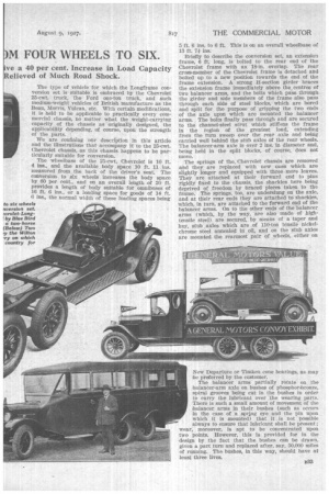
rectified beyond recognition. • The type of vehicle for which the Longframe conversion set is suitable is embraced by the Chevrolet 25-cwt. truck, the Ford one-ton truck, and such medium-weight vehicles of British manufacture as the Bean, Morris, Vulcan, etc. With certain modifications, it is held to be applicable to practically every commercial chassis, no matter what the weight-carrying capacity of the chassis as originally designed, the applicability depending, of course, upon the strength of the parts.
We are confining our description in this article and the illustrations that accompany it to the 25-cwt. Chevrolet chassis, as this chassis happens to be particularly suitable for conversion.
The wheelbase of the 25-cwt, Chevrolet is 10 ft. 4 ins., and the available body space 10 ft. 11 ins. measured from the back of the driver's seat. The conversion to six wheels increases the body space by 60 per cent., and on an overall length of 20 ft. provides a length of body suitable for omnibuses of 16 ft. 6 ins., or a loading space for goods of 14 ft. 6 ins., the normal width of these loading spaces being to six wheels aversion set. ?vrolet-Long' by Blue Bird a two-horse (Below) Two u, the Wilton -ry on which country for
5 ft. 6 ins. to 6 ft. This is on an overall wheelbase of 13 ft. 7i ins.
Briefly to describe the conversion set, an extension frame, 6 ft. long, is bolted to the rear end of the Chevrolet frame with an 18-in. overlap. The rear cross-member of the Chevrolet frame is detached and bolted up to a new position towards the end of the frame extension. A strong H-section girder braces the extension frame immediately above the centres of two balancer arms, and the bolts which pass through the girder and side members of the frame also pass through each side of steel blocks, which are bored and split for the purpose of gripping the two ends of the axle upon which are mounted the balancer arms. The bolts finally pass through and are secured to the channel-steel strut which stiffens the frame in the region of the greatest load, extending from the turn sweep over the rear axle and being carried well behind the stub axles of the rear wheels. The balancer-arm axle is over 2 ins, in diameter and, being held in the split blocks, of course, does not move.
The springs of the. Chevrolet chassis are removed and they are replaced with new ones which are slightly longer and equipped with three more leaves. They are attached at their forward end to pins rigidly fixed to the chassis, the shackles here being deprived of freedom by braced pieces taken to the frame. The springs, too, are underslung on the axle, and at their rear ends they are attached to shackles, which, in turn, are attached to the forward end of the balancer arms. On to the other ends of the balancer arms (which, by the way, are also made of hightensile steel) are secured, by means of a taper and key, stub axles which are of 110-ton tensile nickelchrome steel annealed in oil, and on the stub axles are mounted the rearmost pair of wheels, either on New Departure or Timken cone bearings, as may be preferred by the customer.
The balancer arms partially rotate on the balancer-arm axle on bushes of phosphorlkonze, spiral grooves being cut in the bushes in order to carry the lubricant over the wearing parts. There is such a small amount of movement of the balancer arms in their bushes (such as occurs in the case of a spring eye and the pin upon which it is mounted) that it is not possible always to ensure that lubricant shall be present; wear, moreover, is apt to be concentrated upon two points. However, this is provided for in the design by the fact that the bushes can be drawn, given a part turn and replaced after, say, 50,000 miles of running. The bushes, in this way, should have at least three lives. Throughout the whale of the conversion set steel stampings are employed, thus giving assurance of durability and reliability. Every part is jig-drilled in order• to facilitate erection, so much so that conversions of existing chassis could be undertaken by any qualified repairer or engineer as, with the necessary instructions available, no difficulty of any sort is presented, It is, however, extremely essential that the balancer-arm axle shall be definitely parallel to the driving axle; otherwise, the stub axle cannot be set truly and the wheels will not properly, track, the result being, of course, undue tyre wear,
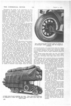
A further point in the conversion to six-wheelers is the entire replacement of the compensating gear for the brakes. The compensating gear normally fitted to the Chevrolet chassis is removed and replaced with a set provided by the manufacturers of the Longframe, which gives more effective brake action and, moreover, provides wing-nut adjustment under the driver's seat for both the hand brake and the foot brake. With the normal arrangement it is necessary to adjust each brake separately, but with the new gear, when once the initial adjustments to each brake shoe have been made in the works, the compensating gear takes care of all the differences that may afterwards occur. The pull is then quite equal, and it is found impossible to lock one wheel without at the same time locking the other.
It is as well here to explain the action of the coupled wheels whenever an obstruction is met. Assuming that the obstruction hit first by the driving wheel is 10 ins, high, the road spring straightens and pushes rearwards the shackle by which the rear end of the spring is coupled to the forward end of the balancer arm. The spring rising, through the wheel passing over the obstruction, then lifts the end of the balancer arm and, the rear wheel forming a fulcrum, the chassis is raised 5 ins, at a point in line with the balancer axle; the rearmost wheel now passing o'er the obstruction lifts and, in endeavouring to depress the end of the road spring, raises the chassis 5 ins, again at the point in line with the balancing axle. Thus, Instead of the chassis frame having been lifted 10 ins. through a single wheel passing over an obstruction 10 ins, high, it is lifted twice, but, in each case, only 5 ins., anti it is now fuily agreed, despite what critics may say, that two light blows are infinitely to be preferred to one heavy blow. This advantage, of course, is material when fragile loads are being
carried and greatly to be appreciated when the vehicle is a passenger-carrier, because road shocks are found to be largely eliminated, the smaller shacks not being noticed, whereas those of larger amplitude cannot be avoided.
The springs being slung below the axle, the centre of gravity is brought materially lower, which, again, is a great advantage when high loads have to be carried.
The mounting of the rearmost wheels on maependent axles, each in turn sprung independently, produces the effect that the road conditions which affect one side of the chassis are not communicated to the other side through the medium of either of the springs or axle shafts. The rear wheels thus being free to move independently of each other, follow the contour of road obstructions, and there is a marked decreaSe in bouncing and shudder.
It is contended that it is practically impossible to overturn the vehicle and it Is a fact that loads are being continually carried in London on Chevrolet-Longframe vehicles to a height exceeding 14 ft. from the ground level, freedom from side sway being very noticeable, the reason being that every rise or fall of the chassis is reduced by a half.
There is nothing whatever in the conversion set that is likely to give trouble, for it is extremely simple, and with Tecalemit lubrication there is no part to wear except, as we have already mentioned, the balancer-arm bushes.
Although we have confined our description of this conversion set to its application to the 25-cwt. vehicle, increasing the capacity thereof to 35 cwt., the Longframe principle can be applied to vehicles of much greater capacity, as, for example, the 10-ton Leyland six-' wheelers
wheeler,