 1
1 2
2 3
3 4
4 5
5 6
6 7
7 8
8 9
9 10
10 11
11 12
12 13
13 14
14 15
15 16
16 17
17 18
18 19
19 20
20 21
21 22
22 23
23 24
24 25
25 26
26 27
27 28
28 29
29 30
30 31
31 32
32 33
33 34
34 35
35 36
36 37
37 38
38 39
39 40
40 41
41 42
42 43
43 44
44 45
45 46
46 47
47 48
48 49
49 50
50 51
51 52
52 53
53 54
54 55
55 56
56 57
57 58
58 59
59 60
60 61
61 62
62 63
63 64
64 65
65 66
66 67
67 68
68 69
69 70
70 71
71 72
72 73
73 74
74 75
75 76
76 77
77 78
78 79
79 80
80 81
81 82
82 83
83 84
84 85
85 86
86 87
87 88
88 89
89 90
90 91
91 92
92 93
93 94
94 95
95 96
96 97
97 98
98 99
99 100
100 101
101 102
102 103
103 104
104 105
105 106
106 107
107 108
108 109
109 110
110 111
111 112
112 113
113 114
114 115
115 116
116 117
117 118
118 119
119 120
120 121
121 122
122 123
123 124
124 125
125 126
126 127
127 128
128 129
129 130
130 131
131 132
132 133
133 134
134 135
135 136
136 137
137 138
138 139
139 140
140 141
141 142
142 143
143 144
144 IMPLE
Page 63
If you've noticed an error in this article please click here to report it so we can fix it.
MECHANICS
FINAL DRIVES, 3
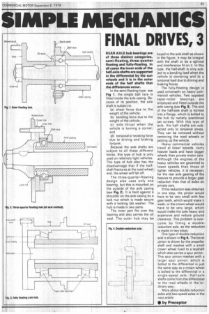
REAR AXLE hub bearings are of three distinct categories, semi-floating, three-quarter floating and fully-floating. In all cases the inner ends of the half-axle shafts are supported in the differential by the sun wheels and it is in the outer ends of the half shafts that the differences occur.
In the semi-floating type, see Fig 1. the single ball race is fitted inside the axle casing. Because of its position, the axle shaft is subject to (a) shear force due to the weight of the vehicle; (b) bending force due to the weight of the vehicle; (c) side thrust when the vehicle is turning a corner; and (d) torsional or twisting force due to driving and braking torques.
Because the axle shafts are subject to all these different forces, this type of hub is only used on relatively light vehicles. This type of hub also has the disadvantage that if the halfshaft fractures at the road wheel end, the wheel will fall off.
The three-quarter-floating design also uses only one bearing, but this is mounted on the outside of the axle casing (see Fig 2). It is held against a shoulder on the axle casing by a lock nut which is made secure with a locking tab washer. The hub is made in two parts.
The inner part fits over the bearing and also carries the oil seal. The outer hub may be keyed to the axle shaft as shown in the figure; it may be integral with the shaft or be a splined and interference fit on it. In this type, the half-shaft is only subject to a bending load when the vehicle is cornering and to a torsional load due to driving and braking forces.
The fully-floating design is used universally on heavy commercial vehicles. Two opposed taper-roller bearings are employed and fitted outside the axle casing (see Fig 3). The end of the half-axle shaft is formed into a flange, which is bolted to the hub by radially positioned set screws. With this type of axle, the half shafts are subjected only to torsional stress. They can be removed without removing the road wheels or jacking up the vehicle.
Heavy commercial vehicles travel at lower speeds, carry heavier loads and have bigger wheels than private motor cars. Although the engines of the heavy vehicles are governed to lower speeds than those of lighter vehicles, it is necessary for the rear axle gearing of the heavies to provide a larger gear reduction than that of axles on private cars.
If this reduction was obtained in one step, the pinion would have to be very small with few gear teeth, which would make it weak, or the crown wheel would have to be very large, which would make the axle heavy and expensive and reduce ground clearance. This problem is overcome by fitting a doublereduction axle, so the reduction is made in two steps.
One type of double reduction axle is shown in Fig 4. The bevel pinion is driven by the propeller shaft and meshes with a small crown wheel fixed to a layshaft which also carries a spur pinion. This spur pinion Meshes with a larger spur pinion, which is bolted to the differential in just the same way as a crown wheel is bolted to the differential in a single-speed axle. Half-axle shafts come from the differential to the road wheels in the ordinary way.
More about double reduction axles and two-speed axles in the next article.
• by Preceptor