


TWO-STROKE OIL ENGINE
Page 49
If you've noticed an error in this article please click here to report it so we can fix it.
lt/rA.NY authorities hold the view that IN_La good deal of the future of the compression-ignition engine is bound up -with the question of the two-stroke cycle of operation. So far, very little has been done in this connection other than with one well-known exception, partly on account of the fact that a great fund of knowledge has been accumulated in connection with the fourstroke cycle for petrol engines. Signs are not wanting that, in some respects, it might be advantageous completely to break away from conventional practice when dealing with oil engines. Possibly something of this nature has been one of the underlying motives behind the evolution of the design.uf Mr. F. H. Ferrah, 39, Felstead Crescent, Ford Estate, Sunderland.
In the patent specification, Mr. Ferrah refers specifically to a fourcyliudered engine, but presumably the number of bores could be varied. Each main or working piston consists of an aluminium casting with a fairly shallow deflector head ribbed internally. Compound piston rings are employed and the gudgeon pin floats in the bosses, which are situated near the base of the working portion of the piston. These bosses are bushed.
An interesting point is that an oilcollecting ledge is formed all around each piston internally and is situated below the third piston ring. From this ledge, holes are drilled to lead the oil to the cylinder walls. Below the apertures leading from this ledge' is the commencement of a light steel sleeve which slips over the long skirt of the piston and the relieved portions of its walls, and is extended outwards and downwards to form the air compressing piston. It has two rings and, of course, works in the enlarged bore forming the lower part of the cylinder casting. This sleeve is secured to the piston by means of two st uds depending from the gudgeonpin bosses. Oil is fed positively to the gudgeon pin, which ix clamped in the small end of he connecting rod. .While on the question of the air compressor, it should be noted that air is drawn hrough a cleaner o a manifold. Its admission is regulated by an automatic mushroom . type valve. After compression in the larger portion of each cylinder bore, air is forced through a spring-loaded valve info a chamber common to all the cylinders, from which it passes to the cylinders when the pistons uncover the transfer ports. Adjustment of the inlet-valve-spring tension is effected by partial rotation of a shaft on which are mounted bellcrank levers coupled to the springs. The eyebolts securing the springs are also adjustable.
In other respects the admission and discharge of gases are effected by the conventional type •of port opened and closed by the piston, as on most other two-stroke-cycle engines. The exhaust ports are uncovered by each piston about 54 degrees before bottom dead centre, whilst the transfer ports are opened some 45 degrees before bottom dead centre.
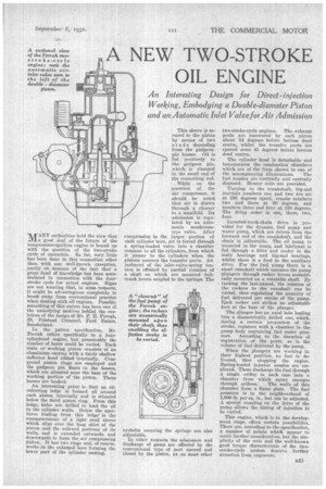
The cylinder head is detachable and incorporates the combustion chambers which are of the form shown in one of the accompanying illustrations. The fuel nozzles are vertically and centrally disposed. Heater coils are provided.
Turning to the crankshaft, big-end journals numbers one and two are set at 180 degrees apart, cranks numbers two and three at 90 degrees, and numbers three and four at 180 degrees. The firing order is one, three, two, four.
Inverted-tooth-chain drive is provided for the dynamo, fuel pump and water pump, which are driven from the forward end of the crankshaft, and the chain is adjustable. The oil pump is mounted in the sump, and lubricant is fed through a filter and cooler to the main bearings and big-end bearings, whilst there is a feed to the auxiliary drive. For the fuel pump there is a small camshaft which operates the pump plungers through rocker levers eccentrically mounted on a rotatable shaft. By turning the last-named, the relation of the rockers to the camshaft can be varied, thus regulating the quantity of fuel delivered per stroke of the pump. litteh rocker end strikes an adjustable foot at the base of the plunger.
The plunger has an axial hole leading into a diametrically. drilled one, which, during a certain proportion of the stroke, registers with a chamber in the pump body containing fuel under pressure. According to the duration of registration .of the ports, so is the volume of fuel delivered by the pump.
When the plungers are working in their highest position, no fuel is delivered, thus stopping the engine. Spring-loaded injector nozzles are employed. These discharge the fuel through a single orifice in each case into a chamber from which spray emerges through orifices. The walls of this chamber form a flame plate. The fuel pressure is in the neighbourhood of 1,004) lb. per sq. in., but can be adjusted. A special coupling on the drive of the pump allows the timing of injection to be varied.
This engine, which is in the development stage, offers certain possibilities. There are, according to the specification, a number of points which appear to merit further consideration, but the simplicity of the unit and the well-known good torque characteristic of the twostroke-cycle system deserve further attention from engineers.