


Patents Completed.
Page 18
If you've noticed an error in this article please click here to report it so we can fix it.
CARBURETTER. — Fulton and Another.—No. 23,697, dated 26th October, 1907.—This carburetter comprises the usual carburetting chamber. (A), and a float chamber (F) -communicating therewith. The carburetting chamber (A) is
divided by means of a partition (Al), and, in the lower portion, liquid fuel is maintained at a constant level by means of the float (B1) and of the valve 1B) in the float chamber (F:. Concentrically arranged within the chamber (A), is a main air inlet tube (G), the lower end of which communicates with the atmosphere and the upper end (G11 is directed towards -the induction pipe (C). A fuel nozzle (J) is provided which extends from the lower end of the chamber (A) up the side of the main inlet tube (G), where it is bent over into the path of the air passing up the air tube. At the bottom of the air tube (G) is arranged a nozzle (II) which is connected to the exhaust or an air pump as desired. It will be seen that, besides air being drawn past the fuel nozzle (J1), on the suction stroke of the engine exhaust gases will be forced past the nozzle on the exhaust stroke.
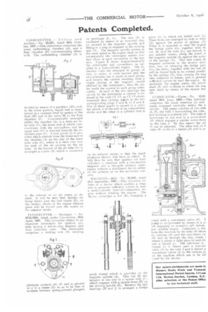
INTERRUPTER. — Henrique. — No. 8713-1908, dated, under Convention, 20th April, 1907. This invention relates to an improved interrupter for ignition systems having a low-tension magneto and four induction coils. The interrupter comprises a rocking arm (Ni carrying
platinum contacts (nl, nil and is pivoted at is to a frame (Q) so as to be free to oscillate between spring-pressed plungers or terminals (F, G). The arm C: is oscillated by means of an eccentric disc (o) secured to the magneto spindle and fitting in a ring (a) engaged in the rocking arm (N). The magneto spindle rotates at the same speed as the engine shaft so that consequentlythe interrupter makes contact twice at each revolution of the former. Figure 3 shows diagrammatically the interrupter and connections as applied to a four-cylinder engine. The induction coils are arranged in groups of two, in series, in such manner that the two primaries are in series in each group, and receive the current resulting from a single closing of the magneto circuit effected by the interrupter ; thus the latter sends the current to each group alternately. At each of the two openings the circuit by the interrupter a current is induced in the coils Cl, C3, or C2, C4 simultaneously thus causing sparks at the two corresponding plugs 1 and 3, or 2 and 4. One of these sparks is caused in a cylinder which is at the end of its compression stroke and the other in a cylinder that is on its exhaust stroke so that the spark produced therein will have no effect. It will thus be seen that ignition for four cylinders is obtained with a low-tension magneto and a two-pole primary interrupter without a distributor device either on the primary or on the secondary current.
MAGNETO.—Bell.—No. 20,986, dated 21st September, 1907.—This invention relates to a device which enables a magneto to generate sufficient current to start a multi-cylinder internal-combustion engine without rotating the engine. 'The device compripes a nut (13), engaging a quick thread which is provided on tin magneto spindle (A). This nut (B) terminates at one end in a square hole C. which engages with a square head (D) on the driving spindle (E). Between the ball bearings (II and J) is arranged a bridge piece (G) to which are bolted rods (Lj These bolts are arranged to slide in tube (Mt against the action of springs (N) When it is required to start the engine the bridge piece (G), together with th nut (13) and the rods (L), are forced, b, any suitable means, along the screw or the magneto spindle (A) against the actio! of the springs (N). This will rotate th magneto armature in the reverse direr tion, but, on releasing the bridge piec (li), the latter, together with the nut (Bj will be forced back to its normal positio by the springs (N), thus causing the ma4 neto armature to rotate, and to generat sufficient current to start the engine. In mediately the engine starts, the drivin shaft (E) will continue to rotate the mat neto shaft by means of the square hea (D).
LUBRICATOR.—Plane.—No. 13,85: dated 30th June, 1908.—This lubricatt comprises the usual reservoir (a) and pump arranged vertically within the r servoir. The pump consists of two tub( (b; hi), the tube b surrounding the tube and working in a barrel (al). The tube (1 terminates at one end in a screw-threa (b21 which engages a similar screw-threa in the tube b. By this means the tut hi can be adjusted. The other end of tt tube (hi, works in a barrel (a5) and is pr vided with a non-return valve )t3). T pump is reciprocated by means of a yt (a4( engaging an eccentric (a3) driven any suitable means. Lubricant is dra from the reservoir by the tube (b1) throe an opening 1156) past the non-return va (b31 and up through the drip nozzle 1 where it passes a sight glass (d) and dr< into a funnel (t). The lubricant in funnel (r) is drawn past a non-reti valve (r1) by the tube b and is forced p non-return valves (f) to the various pr of the machine which are to be tut cated by the device.