


A Disc Brake for Road Vehicles
Page 52
If you've noticed an error in this article please click here to report it so we can fix it.
DISC brakes,once confined to aircraft, are now spreading into the sphere of road vehicles, and patent No.
687,254, shows a design suitable for this purpose. The patentee is M. Straus, 101 West 58th Street, New York, U.S.A.
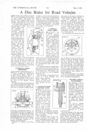
The rotary portion consists of a twopart housing (I) which, when bolted together, gives excellent protection to the mechanism. The stationary members are a pair of rings (2) separated by a row of balls. Each ring is mounted on a -separate splined sleeve (3 and 4) so that they can move with the sleeve yet be axially slidablc. The sleeves , are brought to the outside, where they each carry a lever (5). The two levers are moved by a pair of pistons working in a hydraulic cylinder (6).
The ballraces on the inner sides of the friction-faced discs are formed into cam tracks, so that when the sleeves are rotated, the discs expand or retract in an axial direction. Adjustment is giVen by a setscrew (7) which operates a spreading device between the two levers.
AUTOMATIC BRAKE ADJUSTMENT
A N automatic brake-adjusting unit is rI shown in patent No. 686,691, by A. Tuck and W. Reece, "Granville ", "ry-Mawr Avenue, Rumney, Mon. A feature of the scheme is that it gives automatic centralization of the shoes in the event of the facings wearing unevenly.
The drawing shows the self-adjusting unit, which is located at the ends of the shoes (I) remote from the expander. To each shoe is pivoted a sliding plunger (2) having a bevelled inner face (3). A wedge-shaped abutment (4) engages the ends of-the two plungers and this forms the adjustment. It can be moved in the spreading direction by the turning of a quick-threaded stud (5); this is loaded in the screwing-in direction by an external torsion-spring (6).
Normally, the spring is not strong A42 enough to turn the stud, unless slack be present, in which case it is immediately taken up. The wedge member is free to slide sideways to a limited extent in its housing (7) and this gives the scheme its self-centralizing action. The sliding movement also imparts a two-leadingshoe action to the assembly.
1DATENT No. i 689,035 comes from F. Nal I inger, 22 Relenbergstrasse, Stuttgart, North Germany, and shows a design of light vehicle claimed to give better weight distribution when unloaded and extra space in the cab.
The chassis in this scheme terminates at the front .of the engine, b u t both the driver's cab and radiator project well ahead, the cab having as 18w a floor-level asiground conditions will safely permit. If the engine be of the normal type it divides the seating into two, but a horizontal engine could be accommodated quite easily under the cab seat.
The chassis consists of a central backbone, fitted with a pair of welded crossmembers to meet the springs, which are of the helical type. The radiator may be at the front or it can be disposed behind the cab.
With this scheme, a large body can be carried on a short wheelbase, thus giving good manoeuvrability. Moreover, the load can be evenly distributed between the two a), les, A SINGLE-PLUNGER INJECTION PUMP 'THERE have been one or two patents lately dealing with the subject of single-plunger pumps haying a rotary distributor, and now patent No. 682,698 appears showing a pump with no distributor at all. The injectors are all piped-up together to the pump, and the route of each separate charge is determined by the conditions prevailing in the respective cylinders. The patentees are Bryce Fuel Injection Ltd., and others, Ironbarks Works, Staines, Middlesex.
The controlling factor is the compression existing in the cylinder. As no two compressions occur at the same moment, it can be used to open a valve to each injector in turn. The action takes place in the injector itself and the drawing shows the means adopted.
The injector works on the usual principle, a needle-valve (1) being lifted by the fuel pressure against the force of a spring (2). In this case however, the spring force can be relieved to sonic extent by the Cylinder com pression. This -relief is given by a small piston (3) which responds to the compression which reaches the piston 1.ia a small port (4).
On compression, the piston rises and Jilts the abutment lever (5) of the main spring, so that the particular injector has, for a moment, a weaker closing force than that of the others, and so receives the charge. The compression does not control the timing (the pump does this) but only puts the needlevalvein a state of readiness to inject. A second scheme shows a positive compression-operated valve instead of a spring adjustment.
One of the advantages of the scheme lies in the elimination of mechanically driven distributing arrangements.
ELECTRIC VEHICLE TRANSMISSION I N designing a battery
electric vehicle, it is important that transmission losses be cut to the minimum, owing to the strictly limited quantity of energy available for a journey: A transmission designed with this in view is shown in patent No. 686,235, by G. and C Haig, 49a Thames Road, Chiswick, London, W.4.
The mot o r spindle carries the sun pinion (I) which meshes wit h three planet-pinions (2) mounted on a freely revolving carrier.
The outer annulus (3) is also freely mounted, and the output member can be clutched to either the annulus or the planet carrier, according to which direction of running is required. Using the planet-carrier gives a higher forward, gear, the annulus giving a lower gear in the opposite direction.