


Hercules Omnibuses and Mail Vans.
Page 12

Page 14
If you've noticed an error in this article please click here to report it so we can fix it.
The illustrations which accompany this descriptive article include the details of a bus chassis built by the Hercules Motor and Engineering Company, Limited, of Levens
hulmc, Manchester. ['he elevation and plan give the general view and disposition of the various parts. The chassis has been designed to carry a body with a capacity for 36 passengers. Special care has been taken to have the channel steel forming the framework of sufficiently large section to prevent toe possibility of any saggio in the centre. A glance at the elevation shows one ot the extremely strong side members of the framework, and the heavy dumb irons for carrying the forward ends of the front springs. The main frame is strengthened by flitch plates riveted on, and the whole chassis has been built to conform with the Metropolitan Police regulations. The experience of this company as steam wagon builders has no doubt been found most useful as a means of obtaining reliable data when designing this chassis. The ensrir-' 's vertical, and has four cylinders, with a bore .of -..d a stroke of 6 inches. The cylinders are cast parately, and have inspection plugs over each valve. The 'gine develops approximately 4ob.h.p. at 800 revolutions per minute. Mechanically-operated valves of large diameter are employed, and the exhaust and inlet valves are worked off separate camshafts. One is placed on each side of the crank chamber. The phosphor-bronze gear wheels run in an aluminium gear-case, which is oil-tight and dustexcluding. A centrifugal governor is fitted to the forward end of the inlet camshaft, and this operates a butterfly valve placed in the induction pipe above the carburetter. The rearward end of the inlet camshaft carries a pulley for the strap which drives an oil pump. The question of proper lubrication is, as everyone admits, a most important one, and, after many 1. of different devices, a mechanically
operated pump has been adopted as giving all-round good results. The pump is placed on the dashboard in full view of the driver, who can regulate the supply of lubricant as occasion demands. The crankshaft is turned out of the solid from a steel forging, and the journals and .:rank pins have large wearing surfaces. An automatic carburetter is fitted, and this is provided with an auxiliary valve for regulating the supply of air according to the requirements of the engine at dillerent speeds. With a view to making the vehicle reliable under all conditions two systems of ignition are fitted. These are the Eisemann high-tension magneto, and the usual accumulators and coil; the latter is only used as a supplementary system. Both ignitions use the same coil and plugs, and either can be switched on as desired. The cooling arrangements are ample, and the radiator is of the vertical gilled-tube pattern, with a large surface. A circulating pump is driven off the front end of the exhaust camshaft, and a fan is placed behind the radiator. A leathercovered cone-clutch of large diameter is employed, having a broad face. The clutch pedal is designed to give easy working and to save as much as possible the strain brought upon the driver's knee and thigh when declutching constantly in traffic.
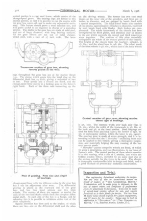
Transmission is by a cardan shaft to the gear box, and from thence by two roller chains to sprockets bolted to the back wheels. The cardan shaft has universal joints at each end, and is shorter than generally found, owing to the unusual length of the gear box. It is turned from mild steel, and is approximately two inches in diameter. A departure has been made from the usual practice with regard to the gear box. It is divided into three parts, the upper and lower portions being merely oil-retaining covers. The central portion is a cast steel frame, which carries all the change-speed gears. The bearing caps are bolted to this central portion, so that it is possible to run the engine with the gear box covers off, and to make any adjustment necksary. This feature should prove a most valuable one, and will prove useful to an engineer in charge of a motorbus service. The shafts in the gear box are made of mild steel, and are of large diameter, with long hearing surfaces. All the gear wheels are cut out of solid chrome nickel steel, with a face of inch wide. The bear ings throughout the gear box are of the marine thrust type. The pinion which gears into the bevel ring on the differential shaft has 24 teeth, giving a reduction of two to one. Four speeds and a reverse are fitted, and the change-speed lever moves in a locking gate at the driver's right hand. Each of the three rods connecting up the
change-speed lever with the different ratios in the gear box
has a nut for adjustment after wear. The differential gearing is placed at the rearward end of the gear box; and has four bevel pinions and two plate wheels. The centres of these are squared to receive the
• ends of the two half-shafts which form the complete differential shaft. At each side of the box is a flange, and by releasing this it is possible to withdraw either end of the shaft completely.
Special attention has been paid to the brakes, of which there are two—one on the differential shaft and the other
on the driving wheels. The former has two cast steel drums on the inner side of the sprockets, and these are 52 inches in diameter, and are gripped by bands lined with a special composition. The back-wheel brake also consists of two drums, approximately iS inches in diameter, encircled by steel bands lined with blocks. Both brakes are compensated. The whole framework of the chassis has been strengthened by flitch plates, and attention may be drawn to the one which connects the second and third transverse stays together. The position of this plate materially strengthens the whole of the central portion of the chassis. The height of the chassis from the roadway, unladen, is 2ft. Sin., and the wheel base is 12ft. 6in. The wheel track of the front wheels is sft. 6in., whilst that of the back wheels is sft. min. The extreme width over back axle caps is 7ft. tin., whilst the width of the framework is sft. Sin, at the back and sft. at the front portion. Steel forgings are used for both front and back axles; the former is 2.1in. by sin. of rectangular section, whilst the latter is sin. square. The steering gear is made of extra strength, and it is interesting to note that the " Hercules " oscillating front axle can be applied to this vehicle, giving a three-point suspension, and materially helping the easy running of the bus over uneven roads.
" Hercules" patent composite wheels are fitted, of which we gave a description, and two illustrations, in our issue of January rith. The central portion of these wheels consists of a steel casting, with a rim of 1J-section, into which are bedded wooden felines, encircled by an outer steel rim of the section suitable for the tyres to be used. The chassis is thoroughly workmanlike both in design and finish, and is a good example of present-day motorbus construction.