


Automatic Coupling for Semi-trailers
Page 58
If you've noticed an error in this article please click here to report it so we can fix it.
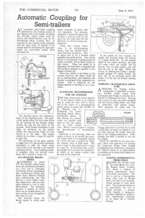
AN automatic semi-trailer coupling operated by the backing action of the tractive unit is the subject of patent No. 651,654, which comes from H. Chalk, and United Dairies, Ltd., 31, St. Petersburgh Place, London, W.2. It operates on the sloping ramp principle, and the chief point of interest is the means used for retracting the legs upon which the semi-trailer stands when disconnected.
The drawing shows the commencement of the coupling action. The semitrailer guide-rollers (I) have been lifted by the backing of the sloping ramps, raising the legs (2) just clear of the ground. With further movement to the right, an abutment on the tractor strikes •the leg-carrying block (3) and moves it to the right. This causes rollers (4) to climb a ramp (5) and lift a plate (6).
The movement of the plate unlocks a toggle lever (7) and permits continued movement to slide the block along rod 8, and so lift the legs to the normal running position. The coupling process is complete when the pivoted crossbeam (9) is nested in socket 10.
ALL-TRAILING BRAKESHOES
ACCORDING to patent No. 652,826, which comes from the Automotive Products Co., Ltd., and L. Chouings, Tachbrook Road, Leamington Spa, leading-shoe brakes give much more effective braking than trailing-shoes, but they develop a much higher working temperature, and are thus more inclined to vary in their effectiveness. The patentees propose a scheme in which there are no leading-shoes, the pivot points being arranged so that they all trail.
The drawing shows the whole system in which each a40
wheel assembly, is fitted with two expanders. For example, expander 1 moves the upper end of shoe 2 and acts also as the pivot for the other shoe (3), the direction of rotation being anticlockwise.
Using only trailing shoes, there is no • self-energizing action, and the applied force must therefore be greater. This is 'taken care of by a booster which amplifies the pedal action. The vehicle drives a continuously running pump (4) which normally drives fluid round an idle circuit. When the pedal (5) is depressed, the fluid flow is impeded and the resultant pressure is applied to the master cylinder (6).
When the vehicle is travelling in the reverse direction, the shoes would all act as leading-shoes, and therefore the booster is arranged to be inoperative in reverse. This is achieved by the simple method of driving it via a freewheel.
AUTOMATIC DECOMPRESSOR FOR OIL ENGINES
THE high compression ratios adopted
in oil engines makes it an arduous task to crank the unit, and to relieve this is the object of a decompressing device shown in patent No. 652,085, by H. Ricardo and C.
Goldsmith, 322, Upper r
Shoreham Road, Shoreham-by-Sea, Sussex. In this scheme, the exhaust valves are forcibly held open so that the engine
can be freely turned over. When a certain speed is reached, the decompressor is automatically tripped.
Referring to the. drawing, when the engine is about to be started, the eccentric rocker shaft (1) is manually rotated by a lever (2) into a position in which the exhaust valve is held open. The lever is kept in this position by a notch in a gate (3). At the same time, a rocking weight (4) is moved into position 5 in which its tail makes contact with the end of the push-rod.
If the engine be now rotated, the weight will oscillate under the tension of a small spring (6). As the turning speed of the engine increases, the time will come when the weight will be thrown over its dead centre, and will then fly over to the right. When this occurs, its sloping face strikes a springloaded plunger (7) which knocks the lever out of its retaining notch and allows it to fly into its normal punning position.
FORGING CRANKSHAFTS FROM
APROCESS for forging hollow crankshafts is described in patent No. 651,860, which comes from Compagnie des Forges et Acieries de la Marine et d'Homecourt, Paris. Starting with a piece of tube, one end is plugged and the interior filled either with sand or, preferably, with molten copper. After plugging the other end, the
forging operation is carried out as with a solid piece of metal, as indeed it is at the time, because the copper does not melt at the forging temperature. After forging, the shaft is heated to run out the copper.
Patent No. 622,938, by the same company, deals with apparatus for forming the crank-web bulges when forging crankshafts from round bars, and patent No. 628,519 relates to an improvement to combine the forming and forging into one operation.
MAKING EXPERIMENTAL PRESS-TOOLS
PATENT No. 651,941, from the Ford Motor Co., Ltd., 88, Regent Street, London, W. I, shows a method of making experimental presstools easily and quickly. The tool is cast in a low-melting point alloy such as Woods metal, but this is not normally strong enough to work sheet steel. The proposed scheme is to super-freeze the tool in liquid nitrogen, a process which imparts a temporary hardness sufficient to enable a few experimental pressings to be taken off it without damage.