


The Automatic Coupling of Trailers
Page 60
If you've noticed an error in this article please click here to report it so we can fix it.
IMPROVEMENTS in the means for lcoupling a trailer to a tractor form the subject of patent No. 409,417, by 0. D. North, P. G. Hugh and Scammell Lorries, Ltd., 52-54, High Holborn, London, W.C.1: The object of the invention is to provide means for coupling the trailer by backing the tractor up to it; at the same time, the temporary supporting wheels of the trailer are lifted and folded away, the reverse action occurring when the tractor is removed.
Referring to the illustration, at the rear of the tractor (left) is a pair of inclined ramps (2), positioned so as to lie in the path of two rollers (3) on the trailer, which is shown standing on its temporary wheels (5). These wheels are carried by struts held in position by a toggle-jointed arm (4), having a roller (6) mounted on its mid-pivot.
The action of backing the tractor is first to lift the trailer by the rollers (3) mounting the ramps. Further movement brings the roller 6 into contact with a cam-track (1), the effect of which is to unlock the toggle and fold up the wheel struts. A locking device, either manual or automatic, then completes the operation.
Fluid Transmission Modifications.
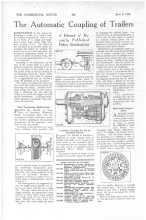
PATENT No. 409,378, by Hans Wach, 57, Seestrasse, RilchbergZurich, Switzerland, deals with improvements in fluid transmission gears, the novelty consisting in the practical arrangement of the apparatus rather than in any new feature.
According to the inventor such gears have, hitherto, been provided with several hydraulic ratios, oi supplementary mechanical change-speed gears. This, he considers, is unnecessary, one hydraulic ratio being sufficient if the point of maximum efficiency be arranged to occur at a ratio of 2 to 1, which gives a starting-torque increase of 3-4 to 1. • The drawing shows the suggested layout, the engine-driven member (1) being in one piece with the gear casing (3). The gear itself follows the Fatlinger principle, an intermediate rotor (shown in heavy lines) being coupled to a brake drum (4) for control,purposes. Behind this brake drum is a free wheel (5) which holds the inter 4f1 mediate rotor against rotation until the speeds synchronize, after which it allows the whole gear to revolve as one. A direct-drive clutch (2) is provided for a straight-through top-gear drive.
A Gearbox Designed for Use by Unskilled Drivers.
patent No. 408,302 is described a gearbox in which changes may be effected with little or no shock, even when used by an unskilled driver. The inventors are the Standard Motor Co., Ltd., and E. G. GrinhanI, both of Standard Motor Works, Canley, Coventry.
The general layout is snore or less normal, the novelty being the method of engaging the selected gears. The drawing shows a four-speed gearbox in which only the first speed is engaged by ordinary sliding gears, the remainder being constantly in mesh ; engagement is achieved by special cone clutches in each pair of gears. Referring to one particular speed, an external cone (6) keyed to the layshaft (1) is moved endwise into contact with an internal cone (4) integral with a constant-mesh pinion (8), thus establishing the drive. Owing to the small size considerable force is needed to transmit the drive ; this is obtained by making the clutch self-energizing. The method used is to mount the external cone on a coarse thread (2) so that the transmitted torque increases the pressure. Control is obtained by an angularly positioned key (5) which, when slid along a groove in the layshaft, rotates the external cone enough to bring it into contact with the internal cone, after which selfenergization supe rvenes.
T h e specification describes also the use of a fluid flywheel in conjunction with this gearbox.
Plate-clutch Improvements.
A MODIFICATION 1—t intended to ensure a more gentle engagement of a plate clutch is shown in patent No, 409,346 by Small and Parkes, Ltd., Hendham Vale Works, Manchester, and G. E. Stanley, 92, Godiva Street, Coventry. The invention consists in the provision of a number of slots in the friction lining of the clutch, extending from the inner periphery partially across the face. The backing plates are so arranged that the friction material is biased into a saucer-like form, so
that the smaller diameter is brought into contact first. This, it is claimed, results in not only a geintler engagement, but in an increased life of the friction fabric.
There is no doubt that a fierce clutch is often the cause of excessive Wear and tear.,