


Supercharging of Road-vehicle Engines F ROM S. A. Andre Citroen, of:Paris,
Page 26
If you've noticed an error in this article please click here to report it so we can fix it.
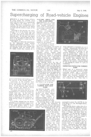
,comes Patent No. 619,978, Which -deals with the cOntrol of a supercharger when fitted to the engine of a road vehicle. The ain't is to proportion auto. matically. the ratio between the degree of boost and the 'resistive torque of the vehicle.
Referring to the drawing, the supercharger (1) is of the Roots type, and is driven via a. bevel shaft and Spiir gears (.2), frOiri.the sun-wheel (3) Of an . .
epicycilic gear. In this gear, the engine driVes the outer ring(4) whilst the final drive to the gearbox is taken from the plartet-carrier (5).
The effect is to drive the supercharger by the differential forces 'existing between road-wheels and engine. Considering the extreme cases; assume that the propeller shaft was locked solid; the engine would then transmit all :IS poe,er ti? the blower and would so calls: the exertion of the grekite.st effort,
Conversely, if the propeller shaft could revolve idly and take ;to power at all, the blower would receive no drive: In the Practical range between these "extremes, the blOwer 'driven harder as the resistance 'increases.
The patent also covers the use of the arrangement as a clutch for starting the vehicle from rest. In this case, the engine, when idling, allows the output shaft to stand still, but as .soon as the speed is increased by the accelerator, a rising driving torque is applied to the shaft.
It is further claimed that the device functions as an automatic torque transformer which makes it possible to nie a two-speed gearbox where a threespeed box would normally be used.
ELECTRIC DRIVE FOR THE AUXILIARIES
DIFFICULTY has always been experienced with large vehicles, particularly those of the articulated type, in providing a suitable drive for auxiliaries such as pump s, air-compressors. hydraulic systems, heaters, -winches and the like, Such is the opinion of Scammell 'Lorries, 'Ltd., TolPits Lane, Watford and others, who suggest, in patent No. 619,562, a versatile electric system for the purpose.
It is proposed to provide an electric generator, clutchable to the main engine, and capable of producing a considerable output, such
20 electrical ii.p. at 200 volts. Suitable ' leads carry the current to individual motors situated where required on the vehicle. For auxiliaries on trailers, the 'scheme is particularly suitable, because only a small cable is needed to connect up. Alternatively, the drawbar can incorporate the necessary electric connections.
The drawing shows, by way of example, h typical use for the scheme. A large tanker needs to have its contents warmed, so five immersion heaters (1) are built in and supplied from the generator. The pump for filling and emptying is also driven by an electric motor (2) .driven from the,same source. I-or controlling the operation of the electrid items, a push-button panel (3) is provided. As the voltage approximates to that of the usual mains supply, the whole system can be
plugged in to the mains when the vehicle is in its garage.
A CULTIVATOR FOR . NARROW ROW-CROP . WORK
A SINGLE-TRACK cult vating machine is shown in patent No. 617,345, by J. Howie, The Elms, School Road, Salford Priors, Evesham. The machine is pedestrian-guided, and is, intended for working in the narrow spaces between row crops.
The drawing shows a side elevation of the machine, the framework of which consists of a pair of sheet-metal side plates, united by bolts and spacer collars. The mechanical parts are all attached to these side plates; this forms the basis of the patent. The drive is transmitted from the engine (1) via belting (2) and then by a chain (3) and sprocket with a further chain reduction before reaching the trackdriving sprocket (4). The engine may be manually slidable in a fore-and-aft direction so that the belt, by being tightened or loosened, can act a.s a clutch. Alternatively, full chain drive plus clutch and gearbox, can be used.
The implement is carried on .an external framework (5) made in the form of parallel links. These can be adjusted for working height by moving the rear-end about a notched sector (6), the parallel links ensuring that the angle is not altered. The. 'machine is guided by the operator walking behind it, and steering by means of a pair of
handlebars.
IMPROVED FIXING FOR TORSION BARS
THE.ends of a torsion-bar _spring have to be_rigidly attached at their anchorage points, and a favouriW method is to use a whited connection. Splines are, however, expensive to make, and have the disadvantage that
they weaken the bar. This view is expressed in patent No. 619,790, by the Ford Motor Co., Ltd„ 88, Regent Street, London, W.I.
The drawing shows a plan view of an improved torsion-bar suspension system in which 1 is one of the bars. its ends are bent back on themselves, as at 2, to form a U-shape, and these form the anchorages At one end the rod passes through a sleeve (3) in the wishbone link, and is bent round to re-enter a hole (4) in the same member.
At the rear or anchorage end, the rod rests in a half-round notch (5) in a channel-section cross-member and the extreme end (6) is tucked, inside the channel. Adjustment for initial setting is_obtained by the inserhon of a shimblock between the spring and the channel, in which position it is secured by a screw.