


Patents Completed.
Page 20
If you've noticed an error in this article please click here to report it so we can fix it.
Crankshaft Lubrication. Fan for Carburetter. Water Injection.
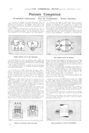
E. Ili:GA.711, No. 20,385, dated 9th September, 1913.—In some engines the camshaft is arranged in the bottom of the crankcase and operates in the oilbath. When this is the case, wheels or discs may be mounted on the camshaft to serve as oil throwers.
One is fitted for each crank-pin, so that the oil is thrown directly on to the pin, and one is also provided for each of the main crankshaft bearings. The oil is forced into a pipe which delivers it on to the bearing in the usual manner.
By thus doing away with the ordinary rotary pump, the lubrication system is much simplified, since no suction pipe is required and the only oil-ducts necessary are those carrying oil up to the main bearings. This system is intended to supersede the chain lubrication which has hitherto been used in engines where the camshaft is situated in the oilbath.
J. D. ROOTS, NO. 29,968, dated 30th December, 1912.— Water has sometimes been injected into the cylinder of an internal-combustion engine on the power stroke to moderate, o: delay, the combustion, but. it. also affects the completeness of the eombustion and its effectiveness, if the water be allowed to mix with the gases before they are completely burnt.
According to this invention the fuel is injected into the cylinder by a. central valve, and there is a number of watervalves surrounding it., by which water is injected into the cylinder immediately after the injection of the fuel is completed. The air in the cylinder is compressed to a sufficient degree to ignite the fuel directly it is injected.
A flange may be provided on the inside of the cylinder head to surround the fuel-valve, so that the fuel and water injected into the cylinder are kept separate from one another.
In another construction an upstanding flange on the piston is arranged to surround the depending fuel-valve flange, and thereby more completely separate the combustion space from the surrounding space into which the water is injected. The injection water is taken from the cylinder jackets, and these may be allowed to become much hotter than is done in normal practice, thereby improving the engine efficiency. A. WILDERS, No, 2796, of 191.3, dated under the biter national Convention, 16th February, 1912.—This specification describes an attachment for a carburetter to improve the mixture of air and gas by rendering it more homogeneous; this is achieved by arranging that the flow of the mixture rotates the fan which thereby assists the mixing. As hitherto made, these fan-mixing devices are open to the objection that the fan is driven too quickly, which causes an increase in fuel consuMption. According to the present con struction two sets of fan blades are mounted on the revolving element and have their blades set at, opposite pitches. The pitch of one, however, is greater than the other so that a differential action is obtained, and the fan runs much more slowly than it would otherwise.
In one form of construction, the casing is screwed on to the top of the carburetter proper, and the mixture passes upwards into it. Suitable hearings carry the rotating element, which comprises the two fan blades, with a perforated disc in between them. All these three parts are fixed on the spindle, which revolves freely in its bearings. The central perforated disc extends into a recess in the wall of the casing, and serves as a protection against any back-firing into the carburetter.
DEUTSCHE WAFTEN UND MUNITIONSFABRIKEN, No. 19,347 of 1913, dated under the International Convention 30th September, 1912.—In thrust-bearings having two rows of balls side by side it has been customary to provide separate racerings for each low of balls, and somewhat complicated devices are incorporated to distribute the load uniformly.
According to the present invention both rows of balls are served by a common race-ring; the load is applied to this race-ring on an upstanding ridge situated above and between the two rows of balls.
In the construction illustrated, a pressure-ring is engaged by a shoulder on the shaft and is seated on the ridge of the race-ring. The position of the ridge on the race-ring, relatively to the two rows of balls, determines the ratio in which the load is distributed between them.