


Worm Contact.*
Page 14
Page 15
If you've noticed an error in this article please click here to report it so we can fix it.
Fig. 7 represents a section of the worm-wheel by the plane CC situated on the side of BB opposite to -AA and at the same distance from it. It should be noticed that the sections aaa, tee, in Figs. 3 and 4, are se •es of he worm-threads planes
symmetrically situated wit, erenee to the central plane 1313,
and that either may be re„.ed as the obverse of the other. :that is to say, cec, Fig. 4, presents the same appearance to an observer in front of the plane of the diagram a_' , Fig. 3, presents to an observer situated at the back of the plane of the diagram. In the same way the section yyyy, Fig. 7, which is the conjugate or envelope of the successive positions of ecr, Fig. 4 is merely the obverse, of the section www, Fig. 6, which is the conjugate of crux, Fig. 3. Regarded in this way the whole surface of the worm-wheel is realisable, for it is clear that the positions of the planes AA, BB, in Fig. 1, have been selected itt a perfectly general manner. It should be noticed that, as the plane of section is removed farther away from the central section, there is an increasing tendency of the worm-thread to become skewed or distorted, leading to a similar tendency on the part of the conjugate profile of the worm-wheel teeth. The effects of increasing the pitch, or decreasing the pitch diameter of the worm, are precisely similar, skewing or distortion being in each case increased. These statements will become clear on studying Figs. S to 9b.
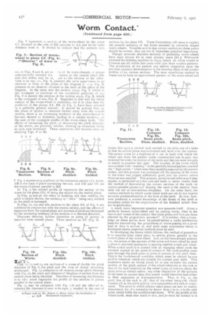
P Fig. 8 represents a quadrant of the transverse section cf a worm. BB is the trace of plane containing the axis, and DD and FE are the traces of planes parallel to BB In Fig. 9 the shaded profile lid represents the section of the worm by the plane DD, bb being the section by the central plane.
In Figs. ga and gh the effect of doubling and then trebling the pitch is clearly shown, the tendency to "skew' being very marked as the pitch is increased.
In Figs. so, roa and sob, sections in the plane EE of Fig. S are exhibited in conjunction with the central section, and the effects of departure from the central plane and increase of pitch are illustrated by the increasing tendency of the sections cc to become distorted.
Diagrams showing further distortion as plane of section is removed from central plane. Three sections on RE (Fig. 8).
Figs.. ii, 12 and 13, are sections of a worm of double the pitch diameter of Fig. 8, the pitch and the form of thread remaining unchanged. Fig. 13 compares in all respects except pitch diameter with Fig. eh, the pitch and distance of the plane of section front the central plane being identical. The effect of increasing the diameter is to very much regularise the profile of the sections in planes parallel to the central plane. Fig. 13 may be compared with Fig. 12b and the effect of increasirg the diameter is seen to be equa y marked in the case of
sections by the plane FE. These illustrations will serve to explain the general tendency of the forms assumed by correctly shaped worm-wheels. Valuable as it is that correct notions on these points should he current, they arc not of immediate practical importance.
Though accurate machine methods of producing worm-wheels have been known for at least seventy years (Sir J. Whitworth patented his hobbling machine in 1835), nearly all worm wheels in cammon use till within late years were east from wooden patterns. The production of the pattern was seldom dependent upon the previous accurate determination in the drawing office of the correct profiles of its various sections. The most expeditious method in vogue was to form an approximate pattern of the worm-wheel and mount this up nil a vertical slid carried on the slide rest of a lathe so that its central plane was horizontal and level with the centres. The actual worm (or a duplicate of it cut in lead) with which the wheel cast from the pattern under construction was to gear, was mounted between the centres of the lathe and the two were brought as nearly as possible into gear. The rotation of the worm which was covered with" marking," in the partially formed pattern, marked the "high points. '' which were then carefully removed by the pattern maker, and this process was continued till the bearing of the worm in the wheel was judged sufficiently good, and the correct centre distance was reached. This process, tentative and tedious as it may appear, is performed at a less cost and leads to better results than the method of determining the correct sections of the teeth on various parallel planes and shaping the teeth to the marked lines with the aid of intermediate templates. On the other hand, the various methods by which worm-wheel teeth are cut do not require accurate predetermination of the form of the teeth. So that, however produced, a correct knowledge of the forms of the teeth is necessary rather for the tomistehoosion of the finished article than for its production.
A much more important question now presents itself. Given a perfectly formed worm-wheel and its mating worm, what is the nature and extent of the contact that takes place, and how are these affected by the proportions assumed ? It is evident that a knowledge on these points must be gained before a really satisfactory basis for determining the proportions of worm-gearing for a given load or duty is aerived at, and until some satisfactory theory is developed purely empirical methods must be used.
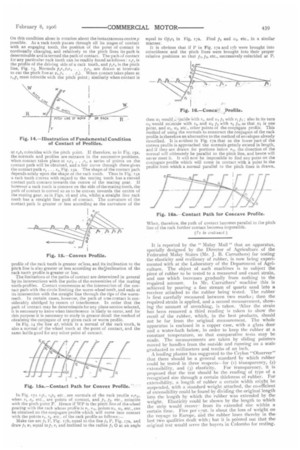
In developing the theory which follows, the method of procedure is to examine what takes place in various planes parallel to the central plane of the worm-wheel. And, as has been already pointed init, the action at the sections of the worm and worm-wheel by such a plane is precisely analogous to gearing together a rack and wheel. 'hen a rack tooth is in contact with an engaging wheel tooth the common normal at the point of contact of the tooth-profiles must pass through the pitch point or point of contact of the pitch lines. This is the fundamental condition Which must be obeyed by any profiles whatever which are suitable for correct gear teeth. This statement needs no formal proof, for at any moment the correct motion of the pitch surface of the wheel relatively to the rack or that of the rack relatively to the wheel is one of rotation about the pitch point as virtual centre ; any other disposition of the surfaces of the teeth in coniact than that stated would therefore lead either to their separation or interpenetration. Thus in Fig. /4 the pitch line of the rack is /R.; that of the wheel being .W, which touches 02 at the pitch point ; rr is one position ot a rack or wormtooth. The point at which contact takes place can now be readily determined, ior, if a normalta be drawn from/3 to sr, a is the only point which fulfils the condition laid down. WW, the profile of the wheel-tooth, must also touch ; r at a, and pa must be normal to it On this condition alone is rotation about the instantaneous centrep possible. As a rack tooth passes through all its stages of contact with an engaging tooth, the position of the point of contact is continually changing, and relatively to the pitch lines its path is determinable and is termed the path of contact. The path of contact for any particular rack tooth can be readily found as follows r,r„ is the profile of the driving side of a rack tooth, and p16,, is the pitch line, Fig. 15, Normals pirO2r2 . . . teb, arc drawn at intervals to cut the pitch line at php, . . . p„). When contact takes place at
must coincide with the pitch point ; similarly when contact is at rd, coincides with the pitch pint. If therefore, as in Fig. 15a, the normals and profiles are redrawn in the successive positions, when contact takes place at r,r, . ,r,, a series of points on the contact path will he obtained, and a fair curve through these gives the contact path r, . . . r„, Fig. 15a, The shape of the contact path depends solely upon the shape of the rack tooth. Thus in Fig. r5a a rack tooth convex with regard to the mating tooth has a curved contact path concave towards the centre of the mating gear. If however a rack tooth is concave on the side of the mating tooth, the path of contact is curved so as to be convex towards the centre of the mating gear, as in Figs. 16 and 16a, whilst a straight line rack tooth has a straight line path of contact. The curvature of the contact pails is greater or less according as the curvature of the profile of the rack tooth is greater or:less, and its inclination to the pitch line is also greater or less according as thelinclination of the rack tooth profile is greater or less.
The limitations of the paths of contact are determined in general by its intersections with the paths of the extremities of the mating tooth-profiles. Contact commences at the intersection of the contact path with the circle limiting the worm-wheel teeth, and ends at its intersection with the straight line through the tips of thewormteeth. In certain cases, however, the path of true contact is considerably abridged by reason cf interference. In order that the path of contact may be determinable for any plane section selected, it is necessary to know when interference is likely to occur, and for this purpose it is necessary to study in greater detail the method of obtaining the conjugate of any given rack or worm profile. In Fig. 14 the line at, which is a normal of the rack tooth, is also a normal of the wheel tooth at the point of contact, and the same holds good for any other point of contact.
In Fig. T74, ,h, = 2p2 etc., are normais of the rack profile rir,,, when ri r., etc., are points of contact, and 1.1.1%2. etc., coincide with the pitch point P. Hence if WP is the pitch line of the wheel gearing with the rack whose profile is r1, rib points tvi, w.2, etc., can be obtained on the conjugate profile which will come into contact with the points ri, /.2, etc., of the rack profile as follows :— Make the arc fr, P. Fig. t7b, equal to the line pi P, Fig. 17a, and draw p, w, equal top, ri and inclined to the radius pi 0 at an angle equal to Opiri in Fig. i7a. Find p2 and u.72, etc., in a similar manner.
It is obvious that if P in Fig. r7a and 17b were brought into coincidence and the pitch lines were brought into their proper relative positions so that pi, p2, etc., successively coincided at P.
then re, ■vith i, and Li lit with rip, : also in its turn te, would co:ncide with r,b and tv, p, with r, p2, so that tr, is one point, and tr.2, fro, etc., other points of the conjugate profile. This method of using the normals to construct the conjugate of the rack profile is therefore an alternative to the method of envelopes already described. It is evident in Fig. r7a that as the lower part of the convex profile is approached the normals greatly extend in length, and if they are drawn for portions below r11. the direction of the normal will ultimately be parallel to the pitch line, and hence will never meet it. It will now be impossible to find any point on the conjugate profile which will come in contact with a point in the profile from which a normal parallel to the pitch lines is drawn.
It is reported by the " Malay Mail " that an apparatus, specially designed by the Director of Agriculture of the Federated Malay States (Mr. J. B. Carruthers) for testing the elasticity and resiliency of rubber, is now being experimented with at the Laboratory of the Department of Agriculture. The object of such machines is to subject the piece of rubber to be tested to a measured and exact strain, and one which increases gradually from nothingto the required amount. In Mr. Carruthers' machine this is achieved by pouring a fine stream of quartz sand into a receiver attached to the rubber being tested. The rubber is first carefully measured between two marks ; then the required strain is applied, and a second measurement, showing the amount of stretching, is taken. 'After the strain has been removed a third reading is taken lo show the recoil of the rubber, which, in the best products, should not be far from the original measurement. The whole apparatus is enclosed in a copper case, with a glass door and a water-bath below, in order to keep the rubber at a constant temperature, so that comparative tests may bemade. The measurements are taken by sliding pointers. moved by handles from the outside and running on a scalegraduated to millimetres and tenths of an inch.
A leading planter has suggested to the Ceylon "Observer"' that there should be a general standard by which rubber could be tested in three respects—for (I) transparency, (2).
extensibility, and (3) elasticity. For transparency, it is proposedthat the test should be the reading of type of a recognised size through a certain thickness of rubber. For extensibility, a length of rubber a rertain width might be suspended, with a standard weight attached, the co-efficient of extensibility coeld be found by dividing the original length into the length by which the rubber was extended by theweight. Elasticity could be shown by the length to which the strip would recove,from its extended size within a certain time. Five per int. is about the loss of weight on the voyage to Europe, and the rubber loses thereby in thelast two qualities dealt with ; but it is pointed out that theoriginal test would serve the buyers in Colombo for testing