


A Dual-clutch Transmission
Page 66
If you've noticed an error in this article please click here to report it so we can fix it.
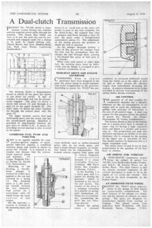
PATENT No. 795,260 shows a transmission system having two clutches and two separate power paths through the gearbox. This "means that whilst one ratio is in use, the next one can be preselected and engaged ready for a change to be made by clutch shifting only. (David Brown and Sons (Huddersfield), Ltd., Park Gear Works, Lockwood, Huddersfield.)
The drawing shows a diagrammatic layout in which all the gears are shown in one plane for clarity. A pair of clutches is provided and can be alternatively engaged. ' The plate (I) drives a sleeve and pinion (2) and through it a gear (3) on the upper layshaft (4). The other plate (5) drives the lower layshaft (6) through the central shaft and the gears (7).
The upper layshaft carries first and third-speed gears and the lower one has the second-speed gearing. Selection is provided by dog-clutches between the gear pairs as shown at 8. A means for providing reverse gearing is also covered in the patent.
COMBINED FUEL PUMP AND INJECTOR
SAID to be equally suitable for compression-ignition engines, or spark
ignited light-fuel engines, a combined injection pump and nozzle is shown in patent No. 793,620. It is claimed to be simpler and cheaper than the conventional separate pump and injectors. (0. Grigar, Englisch Viertel Strasse 42, Zurich 7(32, Switzerland.) Referring to the drawing, a two-diameter plunger is worked by rocker gear applied to the top and returned by a spring (1). The pumping space is 2, the annulus formed between the two diameters. Fuel arrives via a screw-down valve (3) which forms the main control of fuel output.
On the upstroke, a vacuum is formed in the pumping space and B32 draws in as much fuel as the valve will permit to pass in the time available. On the down-stroke, the trapped fuel rises in pressure and flows through a bore (4) into the space under a spring'-loaded accumulator piston (5). The adjustment of the spring governs the pressure at which the fuel is injected.
As the plunger descends further, a series of fine grooves (6) emerges from the nose and the accumulator then discharges the fuel through them, creating a fan-shaped fine spray of fuel mist in the cylinder.
When used with petrol or other light fuel, the working parts must be lubricated, and the design is arranged to give a constant circulation of oil.
RESILIENT DRIVE FOR ENGINE GOVERNOR CUSHIONED drives to engi ne 1,-, governors have been designed in the past, the object being to avoid transmitting cyclic irregularities to the governor. According to patent No. 795,917 the prc vious methods, such as rubber-mounted gears, take up too much space, and have a fixed natural frequency of oscillation which can be objectionable. The present scheme requires little space and its natural frequency is automatically damped if it arises. (Caterpillar Tractor CoMpany, 800 Davis Street, San Leandro, California, U.S.A.)
In the drawing, 1 is a bevel gear and 2 a pinion for driving the governor, which is mounted at the top of the unit shown. The essence of the drive is a coupling consisting of a number of springsteel laminations (3). These act as a torsionbar, transmitting the drive but not vibrations thereof.
Should the spring attain a resonant condition, its increased deflection would bring the blades up to the edges of slots (4) and in effect shorten the effective length, thus immediately de-tuning the system. A positive abutment drive is also provided to prevent over-stressing of the spring blades during overload.
OIL CONTROL
THE quantity of oil that reaches the combustion chamber has a decisive influence on the oil consumption of an engine and to reach the minimum compatible with certainty of lubrication is the aim of all control rings. A dual ring system for this purpose forms the subject of patent No. 794,620. (G. °spelt, Herrengasse 70, Vaduz, Liechtenstein.)
The section shown is that of the bottom end of a piston skirt; here is located an upper ring (1) having a high expansive force and below it a smaller and weaker ring (2). The proportions are such that the lower one leaves an oil film of .01 mm. thickness; this is reduced by the passing of the upper one to one-tenth of this. The shaded portion (3) illustrates this at a highly magnified scale.
The return bores (4 and 5) are of sizes proportional to the quantity of oil they have to remove.
AIR SPRING FOR VEHICLES
1-1 A PNEUMATIC suspension system
forms the subject of patent No. 792,785. from Recherches Etudes Production R.E.P., 38 Avenue Pierre ler de Serbie, Paris. The chief feature is that the natural resonant frequency of the vertical movement is made to lie in the region of 1.3 cycles per second. This is said to be most acceptable to the human frame.
AN IMPROVED FIFTH WHEEL DATENT No. 794,077 shows improvements in the design of fifth wheels for tractor-trailer combinations. The chief features of the scheme are simplicity and the absence of reliance on small springs. The parts are designed for manufacture mainly.from castings or forgings. The patent comes from American Steel Foundries, 130 East Randolph Street, Chicago, U.S.A.