


Heating the Interior of Buses
Page 62
If you've noticed an error in this article please click here to report it so we can fix it.
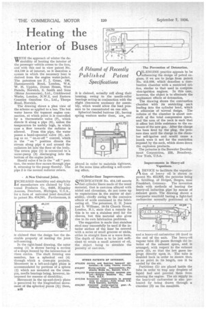
WITH the approach of winter the de sirability of heating the interior of the passenger vehicle comes to the fore, and with this end in view patent No. 414,139 is of interest, as it describes a system in which the necessary heat is derived from the engine water-jacket. The patentees are F. J. Grose, 190, Hammersmith Road, London, W.6, W. H. Upjohn, Dorset House, West Parade, Norwich, S. Smith and Sons (Motor Accessories), Ltd., Cricklewood Works, London, N.W.2, and Eastern Counties Omnibus Co., Ltd., Thorpe Road, Norwich.
The drawing shows a plan view of the scheme as applied to a bus. The hot water leaves the topmost engine con-, nection, at which point it is controlled by a thermostatic valve (7), which directs it along a pipe (6), unless the temperature be unduly high, in which case a flow towards the radiator is allowed. From this pipe, the water passes a hand-operated valve (6), acting as an " on-or-off " control, which in the " on " position directs the stream along pipe 4 and around the radiators let into the floor of the body. The return pipe (1) is connected to a water-pump (3) discharging into the bottom of the engine jacket.
Should valve 5 be in the "off." position, the water flow occurs through pipe 8, returning to the pump thereby. The pipe 2 is the normal radiator return.
• A New Universal Joint.
I NCREASED durability and simplicity
of manufacture are claimed. by Universal Products Co., 6455, Kingsley Avenue, Dearborn, Michigan, U.S.A., for a form of universal joint described in patent No. 414,241. Furthermore, it is claimed that the design has the desirable property of making the joint self-centring.
In the right-hand drawing, the outer casing (1) is shown having a section of a shape formed by the intersection of three circles. The shaft forming one member, has a spherical end (4) through which a cross-pin projects. Movement in a left-and-right plane is accommodated by portions of a sphere (2) which are mounted on the crosspin, needle bearings being, however, interposed for reasons of durability.
Movement in the up-and-down plane is permitted by the longitudinal movement of the spherical pieces (2); these, 1248 it is claimed, actually roll along their housing, owing to the needle-roller bearings acting in conjunction with the slight clearances necessary for assembly, which would allow the load pressure to be concentrated on one side.
Spherical-headed buttons (3), having spring washers under them, are ern ployed in order to maintain tightness, at the same time affording a self-centring effect.
Cylinder-liner Improvements.
SPECIFICATION No. 414,145 asserts that cylinder liners made of the usual material, that is cast-iron alloyed with nickel and chromium, do not come up to expectations in the matter of durability, chiefly owing to the corrosive effects of acids contained in the lubricating oil. The patentees, E. H. Jones and S. Williams, 16-24 Church Street, London, N.1, state that a remedy for this is to use a stainless steel for the sleeves, but this material also gives rise to its own lubrication problems.
The suggestion is made that stainless steel may successfully be used if the interior surface of the liner be covered with a series of small grooves or nicks, either in straight lines or a wave form. The depth of these is to be just sufficient to retain a small amount of oil, the object being to simulate the porosity of cast-iron. The Prevention of Detonation.
(-AIL-ENGINE practice appears to be Llinflueneing thp design of petrol en-. gines, if we are to judge from patent No. 412,539, which describes a combustion chamber with a restricted orifice, similar to that used in compression-ignition engines. In this case, however, the object is to eliminate the unpleasant effects of detonation.
The drawing shows the combustion chamber with Its restricting neck leading into the cylinder bead, which is otherwise of normal design. The volume of the chamber is about onesixth of the total compression space, and the area of the neck is such that it offers but little resistance to the entrance of the new gas. After the charge has been fired by the plug, the pressure rises until the charge in the chamber self-ignites and would cause a knock were it not for the restriction imposed by the neck, which slows down the explosion products.
The patentee is the Brewster Development Corporation, 225, Broadway, New York, U.S.A.
Improvements in Heavy.oil Vaporizers.
A DEVICE to facilitate the vaporize
tion of heavy oil is shown in patent No. 412,928, the patentee being K. Schilling, of Hofgut, Bergen, near Frankfurt, Germany. The invention deals with methods of heating the heavy-oil induction pipe by meang of exhaust gases. The drawing shows a composite manifold having a light-fuel carburetter normally positioned at 6, and a heavy-oil carburetter (4) fixed to the end of the unit. The heavy-oil vapour tube (5) passes through the interior of the exhaust space, and is arranged, with respect to the exhaust ports (2), so that the hot gases impinge directly upon, it. The tube is doubled back in order to ensure that, at no point in its length, can it be cooled by the air.
Partitions (1) are placed inside the tube in order to trap any droplets of liquid fuel and prevent them from entering the engine. The air supply to the heavy-oil carburetter is also preheated by being drawn through a chamber .(3) on the manifold.