


A Twin-axle Suspension System
Page 76
If you've noticed an error in this article please click here to report it so we can fix it.
A SUSPENSION system for multi
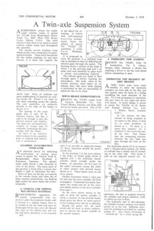
axled vehicles comes in patent No. 735,166, from Hendrickson Motor Truck Co., 8001 West 47th Street, Lyons, Illinois, U.S.A. The chief feature is that there is no metal-to-metal contact, rubber being used throughout the assembly.
The chassis carries brackets from which project four round pins (1) pointing downwards. These form the centres for the rubber cushions (2) and their sleeves; it is these that support the whole load. Pairs of cushions res upon saddle-plates (3) pivoted on rock ing beams (4). Pivots 5 are both on one shaft extending across the vehicle: The axle assemblies are resiliently pivoted to the ends of the beams as shown at 6.
The spacing of the main guide pins is only 18 in. between centres, but this is said to be enough to give the desired control and stability. The axles are restrained horizontally by torque rods (7) resiliently connecting the axlecasings with the frame.
As there is no metal-tometal contact in the assembly, wear is reduced and lubrication is unnecessary.
GEARBOX SYNCHRONISM INDICATOR
AN electrical device for indicating synchronism of mating gears comes in patent No. 734,616, from K. Burgsmueller, Haus Hainberg 1, Kreiensen, Germany. The speedometer cable drives a disc mounted in view of the driver. The input shaft of the gearbox is fitted with a contact that flashes a light to illuminate the disc.
Rows of spots on the disc correspond to the various ratios, and when one of these reaches synchronism, the flashing light makes the spots stand still stroboscopically.
A VEHICLE FOR TIPPING BITUMINOUS MATERIAL
ROAD-MAKING aggregates are N. usually compounded with tar, pitch or other thermoplastic binder and, if carried in a tipping wagon, have to be loaded in the hot state and must be discharged before they cool off. Should they cool on the vehicle they will not tip, and have, therefore, to be returned
B36 to the depot for reheating. A vehicle with self-contained heating arrangements forms the subject of patent No. 735,205 (H. Lawrence, 2 Little Pa r k, Wickham, Hants).
It is proposed to carry the material in a jacketed body and to maintain its heat by deflecting the exhaust gases through the jacket. The drawing shows a section of the body in which 1 is the carrying tank and 2 an outer wall well insulated by glass wool or similar non-conducting material.
The exhaust gases are made to flow through space 3 before reaching the atmosphere. The body, when in the normal position, seats down on an exhaust duct; this parts when tipping is performed so that no uncoupling of pipework has to be done.
SERVO BRAKE IMPROVEMENTS
PATENT No. 733,823 comes from Clayton Dewandre Co., Ltd., Titanic Works, Lincoln, and deals with servos for brake operation. One of the
aims is to provide an improved means for direct operation should the power system fail.
In the drawing, I is the servo piston, 2 the slider to which pedal thrust is applied and 3 the hydraulic master cylinder which actually works the brakes. In operation, the first part of the pedal movement causes the slider to make contact with pivoted beams shown at 4. These beams react on the servo piston.
Further movement closes a valve gap (5) and cuts the servo cylinder off from atmosphere. Continued movement then opens the coned end (6) of the valve and admits suction to the servo cylinder from pipe 7.
As the servo piston moves to the right to work the master cylinder, it exerts a reaction via the pivoted beams which gives the driver an exact pattern of the braking force that he is applying.
Should the power fail, the parts would still all work in direct compression to operate the master cylinder in the normal manner. A PERISCOPE FOR PASSING
PATENT No. 734,661, from G. Annibaletto, Via S. Chiara, Brescia, Italy, discloses a device for enabling a driver to see the road ahead before attempting to pass.
IMPROVING THE RIGIDITY OF DISC BRAKES
1--X A DISC brake must have some
member to unite the hydraulic cylinders on each side of the disc and this usually takes the forth of a bridge straddling the outer diameter of the disc. To avoid springiness in operation, this part must be very rigid and therefore heavy. A better design is shown in patent No. 734,856, by H. Butler and Dunlop Rubber Co., Ltd., 1 Albany Street, London, N.W.1.
In this scheme, the disc, instead of being attached at its centre to the wheel, is held • by its outer periphery as shown at 1. To carry it, a drum like member (2) is attached to the revolving part of the hub. This means that the connecting member between the two sides can pass through the bore of the disc.
The hydraulic piston (3) is in contact with -a friction-faced, presser (4) whilst its cylinder has a central rod (5) extending to the other side. This exerts a pull on the opposite presser (6). In operation, the disc is gripped be ween the cylinder and piston members, both of which are free to float.
The hydraulic unit is self-adjusting, the cylinder having a central boss which screws on to the rod. Sufficient clearance for working is provided by a spring washer (7). Any excess movement is " screwed up" by a clock spring (8).