


A Novel Gearbox Mounting
Page 72
If you've noticed an error in this article please click here to report it so we can fix it.
A Résumé of Recently Published Patent Specifications
A NOVEL method of mounting gear11,„ boxes is described in patent No. 334,199, by Morris-Commercial Cars, Ltd., C. K. Edwards and W. W. Hamill. The main object of the invention an Pears to be, the production of various parts, so that they can be assembled in such a manner that any of three positions of control can be obtained.
With the Same set of parts, machined in the same manner, a chasais can be produced incorporating left-hand forward control, right-hand forward control or a central control position-where the driver is situated behind the engine. ' The specification goes farther than this, and says that even after a chassis has been delivered to a buyer it can be altered from any one of the three forms to another without great expense. •
The bell or flywheel housing which surrounds the flywheel and clutch, is provided with flanges which may form . supports for the gear7control device, which can be moved to either the right or left position. The change-speed lever can be bent forward so as to be in a convenient position. for operation by the driver. When this lever is to be situated in a central position it is
mounted directly on the gearbox.. If desired, the cylinder block may be so constructed that it can be reversed for a right or left-hand control. The support which is opposite that used for the gear-control device can be used for supporting a starter motor or magneto.
For Carrying Heavy Spare Wheels.
PATENT No. 334,387, by 11. F. Clay toll, R. Dean-Averns and P. Meek, all of Karrier Works, Huddersfield, points out that even with moderately sized spare wheels the loading and unloading of them is almost beyond the strength of one man, whilst with the heavier types it becomes impossible for a driver to handle them unless he can obtain help.
The object of the apparatus described
is to provide a means whereby one man can handle the heaviest wheels. Attached to the frame is a bracket carrying a pivot, on which is mounted a seg. mental member carrying reek teeth on its outer edge. On the same pivot two side members can swing, the dia
tance between them being sufficient for a spare wheel to be carried, as shown in full and dotted lines, the full lines indicating its place on the chassis, whilst the dotted lines show the position of the wheel when it is resting on the ground. •
The spare wheel is mounted on a false -hub carrying a pinion, which can engage with the segmental rack, so that kv, rotating the wheel by hand its pinion causes it to roll up the rack with ease until the deSired position is
obtained, when the arms can be locked by a suitable deyice. The rack can then be raised to the position shown in full lines by continuing to rotate the wheel.
Relating to Laminated Glass.
IN patent No. 334,378, by The Libby. Owens Glass Co., of 608, Madison Avenue, Toledo, Ohio, U.S.A., is described what is claimed to be an improvement in the manufacture of laminated glass. The principal claim reads as follows :—A method of producleg laminated glass by skin coating two sheets of glass and interposing a. non-brittle membrane between the skincoated surfaces and uniting the sandwich thus formed to produce a composite structure, characterized by the step of forming the skin coating of a mixture of gelatine and a solvent for the same, celluloSe composition and a solvent _for the same, and a mutual
solvent. • A Novel Form of Carburetter.
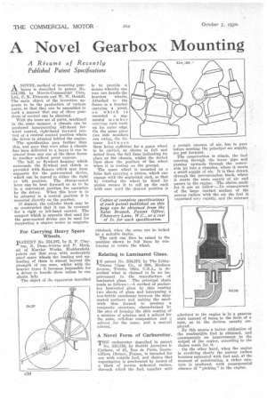
THE carburetter described in patent No. 310,316, by Societe Anonyme le Carbone, of 41, Rue de Paris, Gonnevilliers (Seine), France, is intended for use with volatile fuel, and claims that vaporization is accelerated by means of a block of porous unheated carbon, through which the fuel, together with
n certain anamint of air, has to pass before meeting the principal air supply.,
are put forward. •
The construction is simple, the fuel entering through the lower pipe and passing upwards through the removable jet into a chamber,'where it Meets a small' supplyof air; It is then drawn through the porous-carbon block, where it meets the main supply of air and passes to the engine. . The claims made for it are as follo*:—Inconsequence' of the large contact surface of the porous carbon with the air the fuel is reporized very rapidly, and the mixture
admitted to the engine is in a gaseous state instead of being in the form of a mist, as in the devices usually employed. By this means a better utilization of the combustible fuel is obtained, and consequently an improvement . in the output of the engine, according to the claims made for it.
On the other hand, when the engine is revolving slowly the porous carbon becomes saturated with fuel and, at the moment of accelerating, a richer mixtare is produced, with consequential absence of " pinking " in the engine.