


Patents Completed.
Page 26
If you've noticed an error in this article please click here to report it so we can fix it.
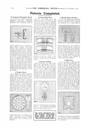
An Improved Detachable Wheel.
J. V. Pugh, No. 21.275, dated 26th September, 1911.—This specification describes an arrangement in which the locking-nut for a detachable wheel is secured without the use of ratchets or other separate devices which have hitherto been regarded as essential. The inner part of the hub in one construction is provided with a centrallyscrewed pin to receive the nut. This nut is coned at its outer edge, and abuts the • outer detachable part of the hub, which is mounted in a fixed position upon the inner part. On the right-hand side of the car, a right-handed thread is used. and on the left-hand side, a left-handed thread, so that, since the friction between the nut and the removable part of the hub is greater than the friction between the nut and the other part, the rotation of the wheels tends to tighten up the nut and keep it locked. Several modified forms embodying this invention are described and illustrated in the specification.
A Wagon Wheel.
B. N. Dodge, No. 23,311, dated 23rd October, 1911.—This invention refers to wheels such as are used on traction engines and other heavy vehicles, and is of the type in which special treads are inserted in a metal wheel. In carrying out this invention a series of metal bars is fixed round the wheel, the bars being under-cut so that a dove-tailed recess is formed between each Emir of adjacent bars. Into this recess there is pushed endwise the tread— which may be of any desired material—such, for instance, as hard wood, cut across tbe grain. The treads are seen red in position by means
cf side rings which are attached to the metal cross-pieces by counter-sunk screws. Any desired pitch of treads may be used. Two are shown in the rdrawings.
Jointing Solid Tires.
H. Gare, No. 25,201, dated 13th November, 1911.—In jointing a solid tire by means of a wire coil embedded in the tire, and twisting a projecting end into engagement with the other end, the spiral is made of square-section material, and is coiled in such a manner that its inner edge forms practically the longitudinal axis of the coil. It will be seen that, when SG arranged, there is little possibility of the coils slipping. The connection may be made by a separate coil engaging the two ends which are
mbechled in the tire. There is also described a tool for cutting out the rubber to allow the entry of the joining section.
A Spring Coupling.
Robert Bosch, Ltd., No. 4598 of 1912, dated under International Convention 22nd March, 1911.—In this spring-coupling one shaft carries a sleeve on which are secured two parallel leaf-springs having a much stiffer plate slating between them. The two leaf-springs engage jaws formed on a disc carried by the other shaft. The advantages of this construction are that the drive can be transmitted in either direction without reversing the bending of the spring ; the only effect of the reversal of drive being that it is transferred from one spring to the ether. The stiff spring in the middle acts as a stop to limit or damp the movements of the other springs.
A Simple Shock Absorber.
B. C. Cox, No. 22,307, dated 10th October, 1911.—In this invention a. pair of ti-rods are hung from a bolt carried by the leaf-spring, and a bottom plate is
fixed on the four ends. The central rod, around which the spring is placed, is fixed on a cross-tree and this engages the side rods by upstanding lugs at each side. The bolt, which pivots the lugs of the cross-tree to the springs, lies between the two legs of the U-members, All the friction and wear is taken by the cross tree, so that the life of the belt is materially increased. The appliance is quickly fitted and detached.
A Solid Tire.
C. R. S. J. Halle, No. 629, dated 9th January, 1912.—This specification describes a twin, tire of the cushion type for motor vehicles. The hollow interior of the tire is of triangular section with th,t flat side or base parallel to the tread. In the accompanying illustration two dotted lines are drawn showing the centre line of the respective treads, and it is stated that the amount of rubber or resilient material on the inside and outside of these lines determines the stiflness of the tire. If there be the same amount of rubber on each side of one of these centre lines, there is no tendency for the treads to be forced apart, and there will be no tension on the bridge. part of rubber connecting the two treads at the bottom of the triangle. If the distribution of rubber is different, however, this bridge will be subjected to tension or compression in a varying degree, so that the design of the tire may be modified to suit. special circumstances. The resilience of this bridge-part is claimed by the inventor to partly absorb the road shocks.