


An Italian Gas-turbine
Page 74
If you've noticed an error in this article please click here to report it so we can fix it.
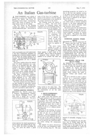
A GAS-TURBINED road vehicle is 1—k shown in patent No. 706,070 (Fiat Societa per Azioni, 300 Corso IV Novembre, Turin, Italy). Compactness and a lbw centre of gravity are the chief claims made for the design.
The unit shown in the drawing includes the engine, the transmission and the differential gear. The turbine is built on principles now well understood; it has three combustion chambers (1) merging into a common exhaust annulus (2) in which the power turbine (3) is located. The first titrbine (4) drives the intake compressor (5) via a tubular shaft (6).
The power turbine drives the central shaft (7) which terminates in a sunpinion in an epicyclic gear (8). This transmits the drive to shaft 9 which carries a free-wheel coupling to the compressor. This comes into action only if the power turbine should run faster than the compressor turbine.
The main transmission comprises gears 10 and II, and a two-speed gear shown generally at 12. The output shaft of this carries the bevel pinion that meshes with the crown-wheel (13).
The latter contains the usual differential gear leading to universally jointed half-shafts on the outside. Should fourwheel drive be required, a second power take-off is provided to drive shaft 14.
POWER-ASSISTED STEERING
PATENT No. 705,372, comes from Gemmer Manufacturing Corporation, Detroit, Michigan, U.S.A., and deals with a design for a powerassisted steering mechanism. The servo
action operates for small movements as well as large, and supplies 80 per cent. of the effort, the driver providing the rest. This gives the driver a good a28 sense of the force he is applying. A feature of the scheme is that the applied force is proportional to the reaction of the torque exerted by the driver.
The drawing shows the layout as fitted to a vehicle. The servo force is created by hydraulic means and originates in an oil-circulating pump (1) carried on the end of the dynamo. The steering column passes through a control valve (2) to a casing (3) containing the usual worm and sector to operate the spindle of the drop arm (4). All this will function whether the power be applied or not.
The servo motor consists of a pair cf opposed cylinders (5) the pistons of which thrust against a small crank on the rock-shaft. One or other of the pistons is energized when pressure fluid is applied to its cylinder, the other one being vented at the same time. The patent describes, in considerable detail, the construction of all the units employed.
A HIGH-COMPRESSION CYLINDER HEAD engine using fuel injection and
spark ignition is shown in patent No. 704,800, by Texaco Development Corporation, New York, U.S.A. The basis of the invention is the shape of the combustion head; this is said to permitthe use of compression ratios between 8 and 13 to I without detonation occurring.
Referring to the drawing, the piston rises almost to the roof of the cylinder so that all the air is forced into chamber 1. This is cylindrical in form, and each of its ends contains, the seating for one of the valves as shown at 2. A partly tangential passage (3) leads the air in and sets up a powerful whirling action during the compression stroke.
The injector (4) sprays downstream of the air flow, and immediately under it is the sparking plug (5). The non
detonating properties are stated to be due to the fact that ignition, starting at the plug, travels upwards against the air flow, so that the actual velocity of flame travel is reduced by the opposition of the air flow.
This results in a comparatively slow rate which tends to become stabilized because as the flame approaches the injector, the mixture becomes richer and therefore burns slower.
The patent goes into the mathematics of the combustion and gives curves showing the value of cylinder and combustion-chamber pressures at various crank angles. The patent also shows the scheme as applied to a two-stroke engine.
HARDNESS TESTING INSIDE HOLES DATENT No. 703,193 comes from D. i Napier and Son, Ltd., 211 Acton Vale, London, W.3, and discloses a device for testing the hardness of interior surfaces of bores. A support extends into the bore and carries a small hydraulic expander, which forces a diamond point into the surface with a predetermined load. The size of indentation, representing the degree of hardness of the metal, can be read off by an optical device.
BREAKDOWN TRUCK FOR HEAVY WORK
ADESIGN for a breakdown truck for dealing with the heavier types of vehicle, forms the subject of patent No. 706,041 (F. Taylor and Sons (Manchester), Ltd., 138 Bolton Road, Salford, 6). A feature is the low overall height which enables the outfit to negotiate bridges and tunnels with safety.
The jib is pivoted at point 1 and is powered by a trunnioned hydraulic ram (2). The jib is provided with a hinged • end portion (3) which can be folded forwards to avoid overhang and to provide a reduced operating radius.
The chief feature is the addition of a folding platform (4) which is suspended• from the jib and is capable of reaching ground level. On this platform can be p aced the axle of the disabled vehicle, instead of unsteadily swinging it on a cable..
When not required for use, the platform can be folded away into the position shown by chain line at 5. It is lifted up to this point by the jib, being guided meanwhile by rollers (6) running in channel members (7).