


Patents Completed.
Page 24
If you've noticed an error in this article please click here to report it so we can fix it.
Duplex Carburation. Leaner Improvements. An Inverted Engine.
Soc. J. CIROUVELLE, H. ARQUEMBOURG ET CIE, No. 18,081 of 1913, dated under International Convention, 10th August, 1912.—In this device a secondary carburetter is used for running at slow speeds and when starting up.
The float chamber on the right supplies the main carburetter by an inclined jet-tube in the main airintake, and the auxiliary air is drawn in past bail valves just below the throttle.
The needle valve in the float chamber is hollow, and is perforated so that the fuel can enter it. A telescopic tube extending upwards from the interior of the needle serves as the jet for the secondary carburetter. This jet opens into a choke tube, which communicates with a lateral passage opening into the body of the throttle, and an auxiliary air inlet is provided at the end of this passage. The throttle is provided with a tapered groove to control the secondary carburetter, and it is so arranged that, when the engine is required to run slowly, the outlet from the secondary carburetter is about half closed.
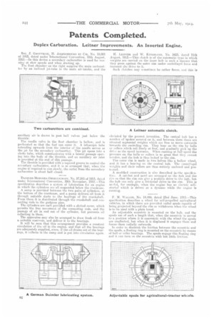
DATNILER-MOTOREN-GESELLSCHAFT, No. 27,545 of 1913, dated under International Convention, 30th November, 1912.—This specification describes a system of lubrication for an engine in which the cylinders are all suspended below the crankcase. A sump is provided between the two pairs of cylinders, at the bottom of the crankcase, and a pump delivers oil from it through suitable ducts to the bearings of the crankshaft. From there it is distributed through the crankshaft and connecting rods to the gudgeon pins. The cylinders are each provided with a slotted cover, which permits the free movement of the connecting rods, and the passage of air in and out of the cylinder, but prevents oil collecting in them. The apparatus may also be arranged to draw fresh oil from a suitable reservoir, and deliver it to the bearings. It will be seen that this arrangement provides a constant circulation of the oil in the engine, and that all the bearings are adequately supplied, since, if the oil drains out of the bearings, it collects in the sump and is put into circulation again. LEITNER and W. KINGSLAND, No. 3423, dated 11th August, 1913.—This clutch is of the automatic type in which ‘veights are carried on the inner hub in such a manner that they press against the miter rim under centrifugal force and transmit the drive to it.
Such clutches may semetimes be rather fierce, and this is obviated by the present invention. The central hub has a number of spokes secured on it, mid between them there are situated segmental weights which are free to move outwards towards the encircling rim. They bear en the rim by balls or rollers which roll freely at first, and gradually pick up the drive as the speed increases, When running at full speed the pressure en the balls or rollers is so great that they cannot revolve, and the hub is thus locked to the rim.
The outer rim is made in two halves like a hollow wheel, and it has a bea-ileg, on the central hub. The centrifugal weights and their rollers are thus entirely enclosed and protected.
A modified construction is else described infrthe specificatioe. A ratchet and pawl are arranged on the hub and the yin se that the rim can give a positive drive to the hub, but the hub ean only give a frictiqual drive to the rim. This is usef id, for example, when the engine has an electric selfstarter which is drivee as a dynamo while the engine is running.
F. M. \VALLEE, No. 14,499, dated 23rd June, 1913.—This specification describes a wheel for self-propelled agricultural vehicles, in which there are provided radial spuds capable of being projected beyond the rim or withdrawn when the wheel is to he used with a plain tread. An adjustable eccentric is mounted on the hub, and the spuds are of such a length that, when the eccentric is moved to a position where it is concentric with the wheel the spuds are unaffected, but when it is displaced it engages them and forces them radially outwards. In order to diminish the friction between the eccentric and the spuds, a floating ring is mounted nn the eccentric by means of ball or roller bearings. The spuds engage this floating ring and it can turn on the eccentric with but little friction: