


Patents Completed.
Page 20
If you've noticed an error in this article please click here to report it so we can fix it.
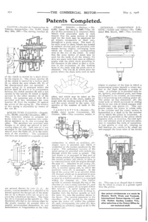
CLUTCH.—Societe de Construction de Vehicles Automobiles.—No. 11,511, dated May 16th, 1907.—The driving member (2) of the c utch is carried by a shaft driven by the engine (1). The driven member (3) of the clutch is carried by a hollow shaft (4) on which the spur wheels (10, 11) of the change-speed gear ate mounted. A spiral spring (5) is arranged within the hellow shaft (4) and it is in compression between the clutch member (3) and a nut carried by the spindle (8) which is rigidly secured to the other member (2) of the clutch. An operating arm or lever (9) is provided and this withdraws the cone member (3) from the member (2) against the action of the spring (5). The tension of this spring is adjustable by means of the nut (6).
BOILER TUBE CLEANER.—Duguid. —No, 26,732, dated 3rd December, 1907.— This inventiou relates to scrapers for boiler tubes and it comprises two cylin
drical members (a, one enclosing the other. The members are provided with flanges (c, d) which are ground to form cutting edges (cl, dl). Saw cuts (h, i) are arranged in the cylindrical members and extend from the holes (hl, 11) to the lower ends of the members. The cylindrical members are mounted on a spindle (e) and are secured thereto by nuts (f, g). An elastic, conical member (k) is adapted to be forced against the flanges (d) of the member (3) by a thumb screw (m) so as to expand the cylindrical members. The member (4) is mounted on the spindle (e). The flexibility afforded to the cutting edges by the elastic member (4) permits them to readily accommodate themselves to any indentations or irregularities in the tube.
CHAIN WHEEL. — Phillips.— No. 5,505, dated 7th March, 1907.—The object of this invention is to construct chain wheels with removable teeth in such manner that the same section of metal used for the teeth may be employed for all wheels, irrespective of their size, throughout a given range. The teeth (1) for each range of chain wheels are formed of uniform section and are provided with shanks having slightly converging faces which are inserted into corresponding slots in the rim, of the wheel. In order that the same section of metal may he used for the teeth. of all the wheels, the slots are made with their axes at different angles with the pitch circle according to the diameter of the wheel so that a variation in the inclination of the working faces of the teeth with the pitch circle is obtained. The line (3, 4) which joins the points where the chain links rock on each other, and which may be taken as the direction of pull on the chain, makes an angle with, the working faces of the teeth, and this angle should be the same, irrespective of the number of teeth in the wheel, CARBURETTE R.—Brasier.—No. 21,934, dated (under Convention), 4th October, 1906.—This invention relates to
carburetters in which an auxiliary, airsupply valve is provided and which is controlled by the suction produced by the engine. The carburetter consists of the usual casing (A) provided with jackets (a), through which hot water is passed. The fuel nozzle (c) is arranged in that part of the casing marked Al communicating with the central portion (A” which, in turn, is in communication with the engine through the pipe (C). Attached to the casing (A), and in communication with the portion (Al), is another casing (Al), in which the auxiliary valve (E) is arranged. At the top of the casing (Al) is an annular drum (D) through which air is permitted to pass into a chamber (d). A conical valve (E), secured to a hollow spindie (e), is arranged within the chamber (d). The hollow spindle (e) extends through the top of the chamber (d) into a small cylinder (F), and is secured to a piston (el) arranged within this cylinder. A spiral spring (f) acts upon the piston (el) and tends to bring it, together with the hollow spindle (e) and the valve (E), into the position shown in the figure. The varying pressures in the chambers (Al, Al) caused by the engine raises the piston (el) within the cylinder (F), and, consequently, the valve (E), thus admitting an auxiliary supply of air to the chamber (Al).
INTERNAL COMBUSTION E N GINE.—Gobiet and Others.—No. 7,565, dated 30th March, 1907.—This invention
relates to engines of the type in which a reciprocating piston imparts a rotary motion to the shaft through a system of cams. A cylinder (a) is provided with inlet, ignition, and exhaust ports, and these are adapted to be covered, or uncovered, by a reciprocating and rotating piston (d). The piston (d) has extensions (d5) the lower ends of which terminate in sliding blocks (a) one side of which engages with a stationary cam groove (o). This cam groove causes the piston to rotate within the cylinder and the rotary motion is transmitted to a shaft (e) by the member (e5) to which the piston is connected. A port hole is provided in the piston which registers with, or uncovers, the inlet ignition and exhaust ports at intervals necessary to complete the cycle of operations. A cam groove or ring (p1), rotating on ball bearings (4), carries a fly wheel (m) and engages the inner sides of the blocks (n). This cam is so shaped the fly wheel to rotate at a than the piston.
that it causes greater speed