 1
1 2
2 3
3 4
4 5
5 6
6 7
7 8
8 9
9 10
10 11
11 12
12 13
13 14
14 15
15 16
16 17
17 18
18 19
19 20
20 21
21 22
22 23
23 24
24 25
25 26
26 27
27 28
28 29
29 30
30 31
31 32
32 33
33 34
34 35
35 36
36 37
37 38
38 39
39 40
40 41
41 42
42 43
43 44
44 45
45 46
46 47
47 48
48 49
49 50
50 51
51 52
52 53
53 54
54 55
55 56
56 57
57 58
58 59
59 60
60 61
61 62
62 63
63 64
64 65
65 66
66 67
67 68
68 69
69 70
70 71
71 72
72 73
73 74
74 75
75 76
76 77
77 78
78 79
79 80
80 81
81 82
82 83
83 84
84 85
85 86
86 87
87 88
88 89
89 90
90 91
91 92
92 93
93 94
94 95
95 96
96 97
97 98
98 99
99 100
100 101
101 102
102 103
103 104
104 105
105 106
106 107
107 108
108 109
109 110
110 111
111 112
112 113
113 114
114 115
115 116
116 117
117 118
118 119
119 120
120 121
121 122
122 123
123 124
124 125
125 126
126 127
127 128
128 129
129 130
130 131
131 132
132 133
133 134
134 135
135 136
136 137
137 138
138 139
139 140
140 141
141 142
142 143
143 144
144 145
145 146
146 147
147 148
148 149
149 150
150 151
151 152
152 153
153 154
154 155
155 156
156 157
157 158
158 159
159 160
160 161
161 162
162 163
163 164
164 165
165 166
166 167
167 168
168 169
169 170
170 171
171 172
172 OVERHAULING THE RUBERY-OWEN M-SERIES TRAILER SUSPENSION
Page 100
Page 101
Page 102
If you've noticed an error in this article please click here to report it so we can fix it.
by R.D. Cater, AMInstBE
TO guide workshop staffs on the methods to be adopted for the fitting and removal of rubber-bushed suspension components on trailers, Commercial Motor last year published two features dealing with the overhauling of the popular Rubery Owen Rseries semi-trailer suspension. (These were published on June 21 and 28.) There are tens of thousands of the Rseries in daily operation, but progress demands change and, the company having introduced the lighter and slightly less expensive M-series unit, I recently returned to the Rubery Owen works to carry out an overhaul of this latest suspension—as before, under supervision of the makers and using the minimum number of special tools.
The M-series does not differ from the R in fundamentals but rather in details. Instead of having the balance-beam assembly carried on tapered rubber-bushes squeezed into the carrier by large-diameter hexagon nuts on a complicated threaded shaft, the M-series utilizes a simple rubber bush moulded onto a nylon sleeve which is a press fit onto the plain shaft. The shaft is in turn a press fit into the carrier and it is retained by a simple, split tubular-pin. The makers expect the assembly to outlast the semi-trailers to which it is fitted and, to judge from the condition of the trailer which we used for the overhaul, they may well prove to be right.
The subject of our exercise was a 30ftlong tandem in service for just over 18 months. Its records showed that it had covered 77,000 miles and the first lesson we learned was an age-old one—be certain when ordering a unit that the builder has done some homework with an eye towards subsequent repair jobs.
A quick look at the layout beneath the trailer between the main frames showed that the air reservoir for the braking system had been mounted low down on the off-side frame. Now, while this had shortened the pipework and presumably decreased the time lag in brake application, it also effectively prevented the centre shaft of the off-side balance beam assembly from being driven out of the carrier housing. Had the job been a roadside one it would, as it turned out, have been an expensive and abortive procedure. Not only was the tank badly situated but the bolts used to secure it to the mounting brackets were far too long for the job. The result was that the excess thread had corroded to such an extent that the nuts could not be run off and at the same time there was insufficient access for a cold chisel to be brought to bear on them.
We were lucky in that we could call fairly quickly on the services of an acetylene cutter with which the tank brackets were cut off.
Some components on a vehicle must, because of their function and other needs, be awkward to get at. When this is the case there is no excuse in my opinion for the makers not expending some thought and a little cash in minimizing the inconvenience. But when inconvenience is caused through thoughtless siting of components, then a fleet engineer worthy of the name should crack down hard on the suppliers and have it altered before it costs him some of his budget and adds a few more square centimetres to his ulcer.
With the tank cleared away we could get on with the job in hand. But it had cost us 14hr, some bruised knuckles and a few strong words, apart from presenting us with the added task of resiting and piping the tank when the job was finished. The lesson is clear: to keep repair costs down one must be one jump ahead of every repair, even as far ahead as the building stage.
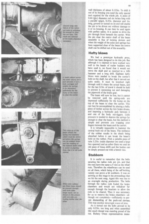
To remove the M-series balance beam, the tubular retaining pin must first be driven out. This pin is 0.5in. in diameter and has a wall thickness of about 0.I25in. To drift it out of its housing you need the only special tool required for the whole job. A piece of 0.44 (in.) diameter rod six inches long with a parallel spigot, 0.25in. diameter and lin. long, ground or turned on its end will enable the pin to be driven out without damage to it or its housing. It can then be used again with perfect safety. It is easiest to drive the pin through from beneath the carrier. With the pin clear the centre shaft of the beam assembly is free of locking devices and when the weight of the axles and springs has been supported clear of the beam the centre shaft can be drifted out of the assembly.
Hefty blows
We had a prototype hydraulic press, which has been designed to do this job. But although it is claimed to have worked very well in the hands of trailer builders who have used it, we found that it would not move the shaft and so resorted to a 14Ib hammer and a long drift. Eighteen hefty blows were needed to break the carrier's hold on the shaft, but after that it moved out quite easily. It must be knocked right through until it clears the actual beam, and for the last 0.5in. of travel it should be held to prevent it cannoning out and damaging the pipework of the brake gear.
The beam will now be free, but it cannot be removed until the spring-ends are depressed sufficiently for the hump on the top of the beam to clear the carrier. This can best be accomplished by placing a hefty piece of timber across the two brake drums, and imposing a hydraulic jack between it and one of the body out-riggers. Little pressure is needed to depress the springs far enough to clear the beam, but this method is simple and prevents you trapping your fingers between the beam and the carrier.
It is virtually impossible to hammer the central bush out of the beam. The resilience of the rubber results in the shock being absorbed before it can break the beam's hold on the rubber. Find a suitable piece of tube 3.25in. inside diameter (we used a large box spanner) and an arbor (here we used an old piece of brass drift) and the bushes can be simply pressed out with a bench vice.
Stubborn
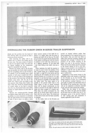
It is useful to remember that the bolts securing the radius rods are iin. and that the nuts have the same a /f size as the wheel nuts. Therefore the wheelbrace can be used on all these, which being of the self-locking variety can prove a bit stubborn. It was on arriving at this stage in the proceedings that we hit the next snag. Again this was due to an oversight during production. The bolts through the radius rods fouled the brake chambers and would not withdraw far enough through the brackets to allow the rods to be cleared. Thus it was necessary for us to remove the brake chambers—although not completely—sufficiently to permit dismantling of the push-rod devises. This was another downright waste of time.
As it turned out the bolts proved to be only 0.25in. too long and when assembled this much thread was standing proud of the nut. Rubery Owen representatives Mune diately put this problem into the hands of their drawing office and assured me that it would get priority attention.
After removing the radius rods it remained only to remove the bushes and fit the new ones. The same system of removal as that for the balance beam was used and we started building up the components ready for reassembly the next day.
Because the bushes used in the M-series gear are parallel, the french chalk treatment used for assembling those in the R-series is not suitable. To fit the parallel type a small quantity of soft soap is needed and with a smear on both the inside of the housing and on the outside of the bush they will slip into position quite easily with the aid of the bench vice. There is only one detail to take into account when fitting these bushes and that is that they should be pressed through to a point where, as the load is removed from the vice, the bonded bush in the rubber projects an equal distance on both sides of the unit.
Because the retaining-pin-hole through the balance beam shaft and its carrier is not jig-drilled, it is most important to remember that the shaft should not be turned round in its hole. If this is done—to utilize a rather better unworn section of the shaft for instance—it is highly likely that the holes in bracket and shaft will not line up. The shaft can of course be turned end for end but then it will require re-drilling and with the bracket in position on the trailer this could prove to be a difficult operation. If you must drill —say when fitting a new shaft—the size is 0.5in.
When replacing the shaft the practice is to mark its end to show the position of the hole. Careful lining up is required because the shaft is a tight fit in the carrier and the retaining pin will certainly not turn it to the lined-up position as it is driven in. It is also necessary to see that the beam is as parallel to the ground as possible as the shaft enters the centre bush. The beam needs to be parallel to the ground rather than to the trailer frame so that no excess torsional stress will be placed continuously on the rubber to account for the angle at which the trailer sits when coupled to a tractive unit. With these two points accounted for, the shaft can be driven home until its ends are flush with the carrier faces. The slotted pin is then driven home and the beam assembly is complete.
As the radius rods on the M-series are carried on bushed rubbers—rather than those comprised of two tapered halves as on the R-series—they are much less likely to suffer from incorrect torquing. Readers will remember how strongly I stressed the importance of the correct torquing of the radius rod ends in the previous features. While the M-series ideally should be torqued to the correct setting of 225 to 250 lb.ft., where a torque wrench is not available it is sufficient to pull the nuts up dead with the wheelbrace, without using either extra leverage or undue force.
Application of the correct torque to the adjustable radius rods remains as important on the M-series as on the R-series. This setting should be 70 lb.ft. As I commented in the previous overhaul features, it is a good idea to position the adjustable rods on the off-side of the running gear where they will not be subjected to excessive amounts of grit, salt and water during bad weather.
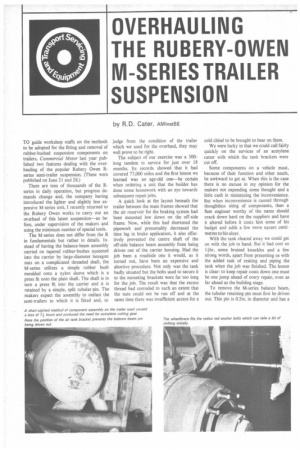
Other than the design of the balance beam, the radius rod ends and the bushes, the M-series does not differ from the R. The information given in the previous features on RO running gear and suspension is equally applicable to..the M-series.