


A Novel Fuel Injector
Page 54
If you've noticed an error in this article please click here to report it so we can fix it.
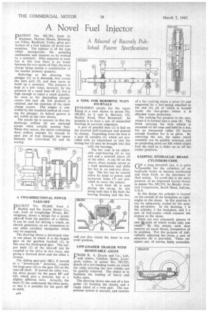
A Rjsum of Recently Published Patent Specifications PATENT No. 582,783, from G. Kammer, Morton House, Mornington Villas, Bradford, Yorks, gives particulars of a fuel injector of novel construction. The injector is of the type which incorporates the pumping mechanism and requires to be worked by a camshaft. Pilot injection is used: but in this case there is no break between the two spurts of fuel, the main charge being merely a continuation of the smaller primary quantity.
Referring to the drawing, the plunger (I), as it descends, first covers the inlet port (2), and then starts to build up a pressure. The pressure is kept at a low value, however, by the presence of a small leak-off (3), but is high enough to inject a small quantity. So soon as the descending plunger covers this leak off, full pressure is attained, and the injection of the main charge occurs. The output is controlled by the standard method of rotating the plunger; its helical groove is not visible in the view shown.
The nozzle tip is unusual in that the discharge orifices (4) are enclosed except when actually passing fuel. When this occurs, the sleeve containing these orifices emerges far enough to eject jets of fuel through the space between the valve-head (5) and its seating.
A TWO-DIRECTIONAL POWER TAKE-OFF
PATENT No. 582,860, from J. Haefeli and the Austin Motor Co., Ltd., both of Longbridge Works, Birmingham, shows a design for a power take-off from the gearbox of a vehicle. It can be used for driving a winch, an electric generator, an air compressor or any other auxiliary equipment which may be required.
The drawing shows a developed view in one plane, in which A is the largest gear on the gearbox layshaft (I), in this case the third-speed gear. The output shaft (2) of the take-off can be coupled to the drive in two ways, one giving a forward drive and the other a erse.
The sliding gear-pair (BC), if moved in a " downwards " direction, couples the large gear (A) to the gear (D) on the take-off shaft. If moved the other way, the drive passes via the gears BF and ED, which give a reversal, but at a slightly different ratio. Actually, the shaft (3) lies underneath the other parts, so that it is possible for the gears BF to mesh. A TOOL FOR REBORING MAIN JOURNALS
jNTENDED mainly for the repair Ishop is a tool shown in patent No. 582,821, by J. and A. Sharratt, 132, Stanley Road. West Bromwich. Its purpose is to bore a row of remetalled bearings in accurate alignment.
A pair of parallel bars (1) is laid on the inverted half-crankcase and secured by clamps. Depending from the bars is a pair of uprights (2), which are provided with an adjustment so that the boring bar (3) may be brought into line with the bearings.
The bar runs in an adjustable cone-bearing (4) at one end and a screwed sleeve (5) at the other. A nut (6) on the sleeve, when turned, serves as a feed mechanism and shifts the bar in an end-wise directiqn. The bar can be rotated either by hand or power, and numerous holes (7) are provided to carry the cutters.
A loose bush (8) is used during the set-up, its size being such that it fits both the hearing housing and the bar, and can thus locate the latter in true axial position.
LOW-LOADER TRAILER WITH REMOVABLE AXLES
FROM R. A. Dyson and Co., Ltd, and others, Grafton Street, Liverpool, comes, fit patent No. 582,925, details of a low-loading trailer on which the axles carrying the rear wheels can be quickly removed. The object is to facilitate the loading of heavy and bulky units.
The drawing shows one end of a box girder (1) forming the chassis and a single wheel of a twin pair. The suspension system is unusual, and consists
of a bar rocking about a pivot (2) and supported by a leaf-spring attached to the end (3), all of which is housed inside the box-girder where it is afforded some protection.
The rocking bar projects to the rear, where it is formed into a cone (4). The bloek carrying the twin wheels is mounted on the cone and held by a nut, but an interposed collar (5) leaves enough freedom for it to pivot. By removing the nut, the entire wheel assembly can be quickly removed, and no projecting parts are left which might foul the load as it slides on or off the trailer platform.
KEEPING HYDRAULIC BRAKE CYLINDERS COOL
rtN a long downhill run, it is quite Is—/possible for the cylinders of an hydraulic brake to become overheated and form froth, to the detriment of their action. To avoid this is the main purpose of an improved layout shown in patent No. 582,512, by Bendix Aviation Corporation, South Bend, Indiana, U.S.A.
In this design the cylinder is located on the outside of the backplate, at rightangles to the shoes. In this position it can be adequately cooled by the passing air-stream. In the drawing, 1 is the cylinder, 2 the backplate, and 3 a pair of bell-cranks which transmit the motion to the shoes.
There are two concentric pistons (4 and 41,. each of which works only one crank. By this means, each shoe receives an equal thrust, irrespective of its position. For the purpose of individually adjusting the shoes, a pair of setscrews (6) is provided. These setscrews are, of course, fairly accessible.