


An Oil-cooled Piston
Page 78
If you've noticed an error in this article please click here to report it so we can fix it.
PAA PISTON provided with an oil circulating system for dissipating the heat is disclosed in patent No. 718,612, by Specialloid, Ltd., black Bull Street. Leeds, 10. The oil flow is
obtained from the main engine-lubrica ing system by tapping itfrom the supply to the gudgeon pin.
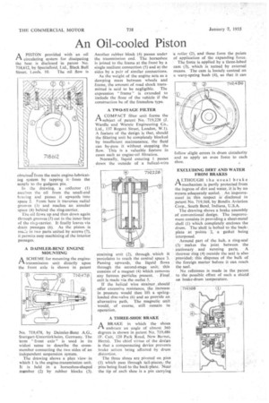
In the drawing, a collector (1) receives the oil from the small-end hearing and passes it upwards into space 2. From here it traverses radial grooves (3) and reaches an annular space (4) behind the ring-carrier.
The oil flows up and then down again through grooves (5) cut in the inner face of the ring-carrier. It finally leaves via drain passages (6). As the piston is ma.,:.2 in two parts united by screws (7), it permits easy machining of the interior passages.
A DAIMLER-BENZ ENGINE MOUNTING
.1-1 A SCHEME for mounting the enginetransmission unit directly upon the front axle is shown in patent
No. 719,478, by Daimler-Benz A.G., Stuttgart-Unterturk helm, Germany. The term "front axle" is used in its widest sense to describe the crossmember connecting the two sides of an independent suspension system.
The drawing shows a plan viewin which 1 is the engine-transmission unit. It is held in a horseshoe-shaped member (2) by rubber blocks (3). Another rubber block (4) passes under the transmission end. The horseshoe is joined to the frame at the front by a single resilient connection (5) and at the sides by a pair of similar connections.
As the weight of the engine acts as a damping mass between wheels and frame, the amount of road shock trans mitted is said to be negligible. The expression " frame " is extended to include the floor of the vehicle if the construction be of the frameless type.
A TWO-STAGE FILTER
1--t A COMPACT filter unit forms the
subject of patent No. 719,228 (J. Wardle and Warnic Engineering Co., Ltd., 137 Regent Street, London, W.1). A feature of the design is that, should the filtering unit be completely blocked by insufficient maintenance, the fluid can by-pass it without stopping the flow. This is a valuable feature in cases such as engine-oil filtration.
Normally, liquid entering 1 passes down the outside of a helical-wire straining unit (2), through. which it percolates to reach the central space 3. Passing upwards, the liquid flows through the second-stage unit; this consists of a magnet (4) which removes any ferrous particles present. Final exit is made via the outlet 5.
If the helical wire strainer .should offer excessive resistance, the increase in pressure would then lift a springloaded disc-valve (6) and so proyide an alternative path. The magnetic unit would, of course, still remain in operation.
A THREE-SHOE BRAKE
I-1 A BRAKE in which the shoes embrace an angle of almost 360 degrees is shown in patent No. 719,486 (F. Catt, 120 Park Road, New Barnet, Herts). The chief virtue of the design is that a compensating device prevents brake action being affected by drum distortion.
The three shoes are pivoted on pins (f) which pass through tail-pieces, the pins being fixed to the back--plate. Near the tip of each shoe is a pin carrying
• a roller (2), and these form the points of application of the expanding force.
The force is applied by a three-lobed cam (3), which is turned by external means. The cam is looSely centred on a wavy-spring bush (4), so that it can follow slight errors in drum circularity and so apply an even force to each shoe.
ENICLUDING DIRT AND WATER FROM BRAKES
A LTHOUGH the usual brake 11 mechanism is partly protected from the ingress of dirt and water, it is by no means adequately sealed. An improvement in this respect is disclosed in patent No, 719,168, by Bendix Aviation Corp., South Bend, Indiana, U.S.A.
The drawing shows a brake assembly of conventional design. The improvement consists in providing a sheet-metal shell (1) which completely encloses the drum. The shell is bolted to the backplate at points 2, a gasket being interposed.
Around part of the hub, a ring-seal • (3) makes the joint between the stationary . and punning parts. A thrower ring (4) outside the seal is also provided; this disposes of the bulk of the foreign matter before it can reach the seal.
No reference is made in the patent to the possible effect of such a shield on brake-drum temperature.