 1
1 2
2 3
3 4
4 5
5 6
6 7
7 8
8 9
9 10
10 11
11 12
12 13
13 14
14 15
15 16
16 17
17 18
18 19
19 20
20 21
21 22
22 23
23 24
24 25
25 26
26 27
27 28
28 29
29 30
30 31
31 32
32 33
33 34
34 35
35 36
36 37
37 38
38 39
39 40
40 41
41 42
42 43
43 44
44 45
45 46
46 47
47 48
48 49
49 50
50 51
51 52
52 53
53 54
54 55
55 56
56 57
57 58
58 59
59 60
60 61
61 62
62 63
63 64
64 65
65 66
66 67
67 68
68 69
69 70
70 71
71 72
72 73
73 74
74 75
75 76
76 77
77 78
78 79
79 80
80 81
81 82
82 83
83 84
84 85
85 86
86 87
87 88
88 89
89 90
90 91
91 92
92 93
93 94
94 95
95 96
96 97
97 98
98 99
99 100
100 101
101 102
102 103
103 104
104 105
105 106
106 107
107 108
108 109
109 110
110 111
111 112
112 113
113 114
114 115
115 116
116 117
117 118
118 119
119 120
120 121
121 122
122 123
123 124
124 125
125 126
126 127
127 128
128 129
129 130
130 131
131 132
132 133
133 134
134 135
135 136
136 137
137 138
138 139
139 140
140 141
141 142
142 143
143 144
144 145
145 146
146 147
147 148
148 149
149 150
150 151
151 152
152 153
153 154
154 155
155 156
156 157
157 158
158 159
159 160
160 161
161 162
162 163
163 164
164 165
165 166
166 167
167 168
168 169
169 170
170 171
171 172
172 11 TEE
Page 64
Page 65
Page 66
If you've noticed an error in this article please click here to report it so we can fix it.
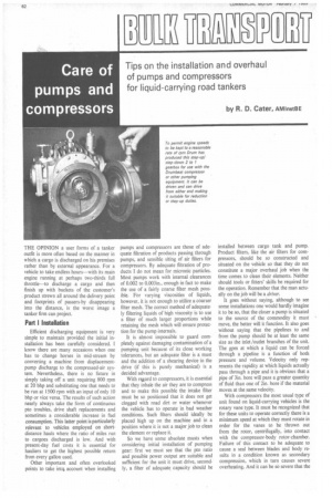
THE OPINION a user forms of a tanker outfit is more often based on the manner in which a cargo is discharged on his premises rather than by external appearance. For a vehicle to take endless hours—with its main engine running at perhaps two-thirds full throttle—to discharge a cargo and then finish up with buckets of the customer's product strewn all around the delivery point and footprints of passers-by disappearing into the distance, is the worst image a tanker firm can project.
Part I Installation
Efficient discharging equipment is very simple to maintain provided the initial installation has been carefully considered. know there are many occasions when one has to change horses in mid-stream by converting a machine from displacementpump discharge to the compressed-air system. Nevertheless, there is no future in simply taking off a unit requiring 800 rpm at 20 bhp and substituting one that needs to be run at 1500 rpm with an input of only 10 bhp or vice versa. The results of such action nearly always take the form of continuous pto troubles, drive shaft replacements and sometimes a considerable increase in fuel consumption. This latter point is particularly relevant to vehicles employed on shortdistance hauls where the ratio of miles run to cargoes discharged is low. And with present-day fuel costs it is essential for hauliers to get the highest possible return from every gallon used.
Other important and often overlooked points to take intc■ account when installing pumps and compressors are those of adequate filtration of products passing through pumps, and sensible siting of air filters for compressors. By adequate filtration of products I do not mean for micronic particles. Most pumps work with internal clearances of 0.002 to 0.003in., enough in fact to make the use of a fairly coarse filter mesh possible. For varying viscosities of liquids, however, it is not enough to utilize a coarser filter mesh. The correct method of adequately filtering liquids of high viscosity is to use a filter of much larger proportions while retaining the mesh which will ensure protection for the pump internals.
It is almost impossible to guard completely against damaging contamination of a pumping unit because of its close working tolerances, but an adequate filter is a must and the addition of a shearing device in the drive (if this is purely mechanical) is a decided advantage.
With regard to compressors, it is essential that they inhale the air they are to compress and to make this possible the intake filter must be so positioned that it does not get clogged with road dirt or water whenever the vehicle has to operate in bad weather conditions. Such filters should ideally be placed high up on the machine and in a position where it is not a major job to clean the element or replace it.
So we have some absolute musts when considering initial installation of pumping gear: first we must see that the pto ratio and possible power output are suitable and sufficient for the unit it must drive, secondly, a filter of adequate capacity should be
installed between cargo tank and pump. Product filters, like the air filters for compressors, should be so constructed and situated on the vehicle so that they do not constitute a major overhaul job when the time comes to clean their elements. Neither should tools or fitters skills be required for the operation. Remember that the man actually on the job will be a driver.
It goes without saying, although to see some installations one would hardly imagine it to be so, that the closer a pump is situated to the source of the commodity it must move, the better will it function. It also goes without saying that the pipelines to and from the pump should be at least the same size as the inlet /outlet branches of the unit. The gpm at which a liquid can be forced through a pipeline is a function of both pressure and volume. Velocity only represents the rapidity at which liquids actually pass through a pipe and it is obvious that a pipe of 3in. bore will pass a greater quantity of fluid than one of 2in. bore if the material moves at the same velocity.
With compressors the most usual type of unit found on liquid-carrying vehicles is the rotary vane type. It must be recognized that for these units to operate correctly there is a minimum speed at which they must rotate in order for the vanes to be thrown out from the rotor, centrifugally, into contact with the compressor-body rotor-chamber. Failure of this contact to be adequate to cause a seal between blades and body results in a condition known as secondary compression, which in turn causes severe overheating. And it can be so severe that the end-plates become blued and badly worn, when the efficiency of the unit will suffer considerably. Make sure that when a compressor is specified, the correct pto ratio enabling the most economical engine speed in relation to the compressor speed and power requirements, is used.
Part II Overhaul
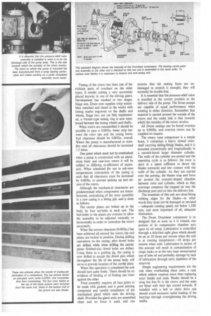
Like all mechanical units, both pumps and compressors suffer the effects of wear _ and tear and I recently spent some time with The Drum Engineering Co. Ltd. of Bradford reliving past experience of pump and compressor overhaul, Drum has in the past four years captured a large percentage of the road tanker pump /compressor market because of its enlightened approach to the industry's problems. For the first time ever it offers a service to operators which provides for complete installations of cargo equipment starting at the vehicle's power source, eliminating the need for users to face the problems of matching speed, power, rotation, and positioning requirements.
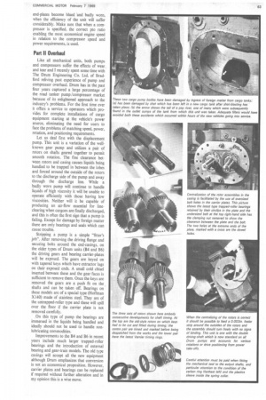
Let us deal first with the displacement pump. This unit is a variation of the wellknown gear pump and utilizes a pair of rotors on shafts geared together to permit smooth rotation. The fine clearance between rotors and casing causes liquids being handled to be trapped in between the lobes and forced around the outside of the rotors to the discharge side of the pump and away through the discharge line. While a badly worn pump will continue to handle liquids of high viscosity it will be unable to operate efficiently with those having low viscosities_ Neither will it be capable of producing an air-flow essential for lineclearing when cargoes are finally discharged, and this is often the first sign that a pump is failing. Except for damage by foreign matter there are only bearings and seals which can cause trouble.
Stripping a pump is a simple "fitter's job". After removing the driving flange and securing bolts around the end-casings, on the older types of Drum units (B4 and B6) the driving gears and bearing carrier-plates will be exposed. The gears are keyed on with tapered keys which have extractor lugs on their exposed ends. A small cold chisel inserted between these and the gear faces is sufficient to remove them. Once the keys are removed the gears are a push fit on the shafts and can be taken off. Bearings on these models are of a special type (Hoffman X140) made of stainless steel. They are of the untrapped-roller type and these will spill over the floor if the carrier plate is not removed carefully.
On this type of pump the bearings are immersed in the liquids being handled and ideally should not be used to handle nonlubricating commodities.
Improvements to the B4 and B6 in recent years include much larger trapped-roller bearings and the introduction of external bearing and gear-train models. The old type casings will accept all the new equipment although Drum emphasizes that conversion is not an economical proposition. However, carrier plates and bearings can be replaced if required without further alteration and in my opinion this is a wise move. Timing of the rotors has been one of the trickiest parts of overhaul on the older types. It entails cutting a very accurately placed keyway in one of the driving gears. Development has resulted in two stages. Stage one, Drum now supplies rotor assemblies matched and timed at the works with timing marks engraved on the shafts and *heels. Stage two, not yet fully implemented, a Vernier-type timing ring is now inter'posed between the timing wheels and shafts.
When rotors are reassembled it should be possible to pass a 0.003in. feeler strip between the rotor tips and the casing bores. End clearance should be 0.005 in. overall. Where the pump is manufactured in stainless steel all clearances should be increased 1.5 times.
One point which must not be overlooked: when a pump is constructed with an aluminium body and cast-iron rotors it will be subject to differing co-efficients of expansion. When scheduled for use in sub-zero temperatures contraction of the casing is such that all clearances must be increased' by 0.003in. to prevent picking up and seizure of the rotors.
Although. the mechanical clearances are predetermined when components are manufactured, centralizing of the rotor assembly in a new casing is a fitting job, and is done as follows.
The carrier plates are bolted up to the body by four set-bolts at each end. The bolt-holes in the plates are oversize to allow the assembly to be adjusted vertically or horizontally in order to centralize the rotors accurately.
When the correct clearance (0.003in.) has been achieved all around the rotors, the end plates are locked in position. During drilling operations on the casing, pilot dowel holes are drilled, while when drilling the carrier plates finished-size dowel holes are drilled. Using these as a guiding jig, the casing is now drilled to accept the .dowel pins which throughout the life of the pump body will serve to provide location of the carrier plate.
When this operation is completed the unit should turn quite freely. There should be no evidence of binding or of fouling one rotor against the other.
Final assembly requires all face joints to be made with gaskets and a good jointing compound and careful. installation of the mechanical gland which seals the driving shaft. Provided the gland units are assembled clean and no force is used, and one ensures that the mating faces are undamaged (a scratch is enough), they will normally be trouble-free.
It is essential that the pressure-relief valve is installed in the correct position at the delivery side of the pump. The Drum pumps are capable of equal performance when rotating in either direction. Remember that material is carried around the outside of the rotors and the outlet side is that towards which the outsides of the rotors revolve.
All Drum casings can be bored oversize up to 0.0601n. and oversize rotors can be supplied on request.
The rotary vane compressor is a simple beast, it comprises a heavy slotted rotorshaft carrying sliding-fitting blades, and it is mounted eccentrically and longitudinally in a smooth-bored larger diameter cylinder. The walls of the cylinder are ported and the operating cycle is as follows: the rotor is spun at a speed sufficient to throw the blades outwards and into contact with thewalls of the cylinder. As they are carried over the porting, the blades trap and force air around the crescent-shaped chamber between rotor and cylinder, which as they converge compress the trapped air into the discharge port and on into the delivery line.
The essentials of this unit are close-fitting rubbing edges for the blades—in other words they must not be damaged or serrated —adequate running speed, not below 1,500 rpm, and most important of all, adequate lubrication.
The Drum Drumbeat compressor is so designed that as soon as it is rotated, one portion of its compression chamber acts upon its oil sump. Lubrication is controlled through a drip-feed sight glass which should be set at 20 drops per minute when the unit is at running temperature-10 drops per minute when cold. Lubrication in excess of this amount will result in contamination of cargo tanks or at the very least unwarranted use of lube oil and probably damage by lack of lubrication through early depletion of the reservoir.
Simple engineering requirements are the rule when overhauling these units, a task which seldom requires more than replacing rotor blades and seals. Blades should be a snug but free fit in the rotors and the seals are fitted with their lips turned inwards. If installed with a belt or chain drive one should avoid excessive radial loading of the bearings through overtightening the driving media.