 1
1 2
2 3
3 4
4 5
5 6
6 7
7 8
8 9
9 10
10 11
11 12
12 13
13 14
14 15
15 16
16 17
17 18
18 19
19 20
20 21
21 22
22 23
23 24
24 25
25 26
26 27
27 28
28 29
29 30
30 31
31 32
32 33
33 34
34 35
35 36
36 37
37 38
38 39
39 40
40 41
41 42
42 43
43 44
44 45
45 46
46 47
47 48
48 49
49 50
50 51
51 52
52 53
53 54
54 55
55 56
56 57
57 58
58 59
59 60
60 61
61 62
62 63
63 64
64 65
65 66
66 67
67 68
68 69
69 70
70 71
71 72
72 73
73 74
74 75
75 76
76 77
77 78
78 79
79 80
80 81
81 82
82 83
83 84
84 85
85 86
86 87
87 88
88 89
89 90
90 91
91 92
92 93
93 94
94 95
95 96
96 97
97 98
98 99
99 100
100 101
101 102
102 103
103 104
104 105
105 106
106 107
107 108
108 109
109 110
110 111
111 112
112 113
113 114
114 115
115 116
116 117
117 118
118 119
119 120
120 121
121 122
122 123
123 124
124 125
125 126
126 127
127 128
128 129
129 130
130 131
131 132
132 133
133 134
134 135
135 136
136 137
137 138
138 139
139 140
140 141
141 142
142 143
143 144
144 145
145 146
146 147
147 148
148 149
149 150
150 151
151 152
152 153
153 154
154 155
155 156
156 157
157 158
158 159
159 160
160 161
161 162
162 163
163 164
164 165
165 166
166 167
167 168
168 169
169 170
170 171
171 172
172 Becorit low loader trials
Page 48
If you've noticed an error in this article please click here to report it so we can fix it.
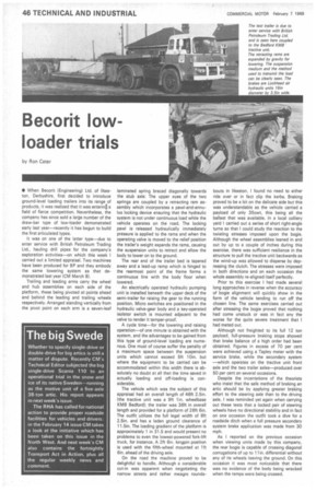
by Ron Cater • When Becorit (Engineering) Ltd. of Ilkeston, Derbyshire, first decided to introduce ground-level loading trailers into its range of products, it was realized that it was enterin6 a field of fierce competition. Nevertheless, the company has since sold a large number of the draw-bar type of low-loader demonstrated early last year—recently it has begun to build the first articulated types.
It was on one of the latter type—due to enter service with British Petroleum Trading Ltd., hauling drill pipes for the company's exploration activities—on which this week I carried out a limited appraisal. Two machines have been produced for BP and they embody the same lowering system as that demonstrated last year (CM March 8).
Trailing and leading arms carry the wheel and hub assemblies on each side of the platform, these being pivoted at points ahead and behind the leading and trailing wheels respectively. Arranged standing vertically from the pivot point on each arm is a seven-leaf laminated spring braced diagonally towards the stub axle. The upper eyes of the two springs are coupled by a retracting ram assembly which incorporates a pawl-and-annulus locking device ensuring that the hydraulic system is not under continuous load while the vehicle operates on the road. The locking pawl is released hydraulically immediately pressure is applied to the rams and when the operating valve is moved to the relief position the trailer's weight expands the rams, causing the suspension units to retract and allow the body to lower on to the ground.
The rear end of the trailer bed is tapered away and a lead-up ramp which is hinged to the rearmost point of the frame forms a continuous line with the body floor when lowered.
An electrically operated hydraulic pumping unit is installed beneath the upper deck of the semi-trailer for raising the gear to the running position. Micro switches are positioned in the hydraulic valve-gear body and a key-operated isolator switch is mounted adjacent to the valve to render it tamper-proof.
A cycle time—for the lowering and raising operation—of one minute is obtained with the system, and the advantages to be gained from this type of ground-level loading are numerous. One must of course suffer the penalty of a maximum space between the suspension units which cannot exceed 5ft 10in, but where the equipment to be carried can be accommodated within this width there is absolutely no doubt at all that the time saved in actually loading and off-loading is considerable.
The vehicle which was the subject of this appraisal had an overall length of 46ft 2.5in. (the tractive unit was a 9ft 1in. wheelbase KMB Bedford): the trailer was 36ft in overall length and provided for a platform of 26ft 6in. The outfit _utilizes the full legal width of 8ft 2.5in. and has a laden ground clearance of 11.5in. The loading gradient of the platform is approximately 1 in 31.5 and would present no problems to even the lowest-powered fork-lift truck, for instance. A 2ft 6in, kingpin position is used with the fifth-wheel mounted at 1ft 6in. ahead of the driving axle.
On the road the machine proved to be delightful to handle. Although a considerable cut-in was apparent when negotiating the narrow streets and rather meagre rounda bouts in Ilkeston, I found no need to either ride over or in fact clip the kerbs. Braking proved to be a bit on the delicate side but this was understandable as the vehicle carried a payload of only 35cwt, this being all the ballast that was available. In a local colliery yard I carried out a series of short right-angle turns so that I could study the reaction to the twisting stresses imposed upon the bogie. Although the wheel assemblies leaned in and out by up to a couple of inches during this exercise, there was sufficient resilience in the structure to pull the tractive unit backwards as the wind-up was allowed to disperse by depressing the clutch. The stresses were imposed in both directions and on each occasion the whole assembly re-aligned itself perfectly.
Prior to this exercise I had made several long approaches in reverse when the accuracy of bogie alignment will quickly show in the form of the vehicle tending to run off the chosen line. The same exercises carried out after stressing the bogie proved that nothing had come unstuck or was in fact any the worse for the quite severe treatment that I had meted out.
Although not freighted to its full 12 ton payload, full-pressure braking stops showed that brake balance of a high order had been obtained. Figures in excess of 70 per cent were achieved using a Tapley meter with the service brake, while the secondary system —which operates on the tractive unit front axle and the two trailer axles—produced over 50 per cent on several occasions.
Despite the incantations of the theorists who insist that the safe method of braking an artic should be by applying greater braking effort to the steering axle than to the driving axle. I was reminded yet again when carrying out these tests that a locked pair of steering wheels have no directional stability and in fact on one occasion the outfit took a dive for a roadside ditch when a full pressure secondary system brake application was made from 30 mph.
As I reported on the previous occasion when viewing units made by this company, the rear bogie is capable of crossing diagonal corrugations of up to 11 in. differential without any of its wheels leaving the ground. On this occasion it was most noticeable that there was no evidence of the body being wracked when the ramps were being crossed.