


A REAR-AXLE EPICYCLIC GEAR.
Page 28
If you've noticed an error in this article please click here to report it so we can fix it.
Quite an interesting change-speed gear is outlined in specification 'No. 172,503, which, actually emanating from :the Perfecto Gear Differential Co., of U.S.A., is entered on the Patent Office records by J. S. Withers It is of the epicyclic type, affording two speeds, and is designed to be mounted inside the rearaxle casing, being, as a matter of fact, part of the main differential gear.
a Descriptions and drawings are included with the specification, which show the invention as applied to either a bevel-driven axle or to one .of the worm and wheel type. The principle involved is, however, the same in both cases, and we will, therefore, confine ourselves here to a reference to one of them, the beveldriven, type, an illustration of which appears on this page.
• Actually, the rear-axle gear in this construction appears almost to be a dif
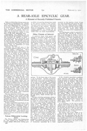
ferential within a differential. There are most certainly two differential cases, one within the other, and of them the outer one is bolted, in the customary fashion, to the crown wheel of the main bevel gears. The bolts which join the halves of the outer case, and secure it to the crown wheel, also serve to support the outer ring, or master gear, of an epicyclic gear of the spur-wheel type. The planetary pinions of this gear are Mounted on spindles or pins' which are really extensions of the joint bolts of the. inner, or ordinary, differential case. It is apparent from this that the, outer gear is' fastened to, and therefore revolves with, the main crown bevel, while the planetary pinions, considered as a whole, are similarly secured to the rear axle differential case, which, of course, transmits the drive to the live axle shafts themselves, in the ordinary way. The third element of the gear, the sun wheel, is a sliding one. esides hayine teeth which mesh with those of the planetary pinions, it has others which may be brought into engagement with those of a gear which is bolted to the rear-axle case and iItherefore stationary. So engaged, the drive is transmitted from the main bevel to the master gear, through the planetary pinions, which revolve round the stationary sun wheel, to the differential case, which revolves, more slowly than the main bevel. This constitutes the first, or low-speed, gear.
The sun wheel may be slid into a position in which it is out of gear with the stationary wheel, while still in gear with the platietary pinions. So arranged, the epicyclic gear revolves idly—churns, as it were—no power is transmitted, and the gear is in neutral.
Fmther longitudinal movement of the sun wheel brings a portion of its main circumference into engagement with a gearwheel, which is actually bolted to the main differential case and, incidentally, to the pins on which the planetary pinions are mounted. The epieyclic gear is thus locked, and a direct drive is then obtained between crown bevel and differential gear.
Vulcan Differential Locking
The Vulcan Motor and Engineering Co., Ltd., patent in No. 172,843, the extremely .simple differential locking gear 434 to which reference has already...been made in the general columns 'of this journal. The inner ends of the two live axle shafts are formed as dog clutches. Normally these are disengaged, but they may he coupled together, for locking, by the manipulation of a screw in the hub cap, which slides one shaft longitudinally.
Other Patents of Interest.
A combined front wheel guard and bumper is described in specification No. 172,4126, by F. It. L. Stott. A substantial hollow bumper, of the usual shape, so far as its exterior is concerned, is supported by brackets frOm the front end of the chassis frame. Within it, and mounted on a spindle, which is articulated so as to allow. it to conform with the shape of the bumper, is a shield or apron. Normally, the apron stays within the bumper, rolled upon the shaft, and it is maintained in that position by suitable
springs. To the lower edge of the apron a rod is attached. Suitable mechanism couples the rod to a pair of plungers carried within horizontal cylinders disposed at the side of the chassis. Compressed air is supplied to these cylinders, under control of the driver from a reservoir located on the chassis, and replenished, as the need arises, by the engine. Movement of the piston forward, under the influence of the compressed air, lowers the apron nearly to the ground : on the supply of air being cut off the pistons retreat towards the rear of the chassis and lift the apron, which rewinds upon its spindle.
The gear-selecting mechanism which is the subject of patent specification No. 172,448, be J. Blackburn, is of that type in which the choice of gear is made by the driver, who moves the gear-change lever accordingly before touching the clutch pedal. Subsequently, when the clutch is released, the gear chosen is automatically engaged. The whole of the mechanism is self-contained, and does not of necessity -form an integral part of the gearbox itself ; it is, apparently, adapted for application to existing chassis. There are a couple of drums, and a set of tappets, or levers, mounted in a box. The levers are mounted on extensions of the selector rods of the gearbox. The drums are fitted with projections designed to engage one or other of the levers. Rotation of the drums, by means of mechanism controlled by a lever
mounted on the steering wheel, brings the right. projections into place for operating the lever which governs engagement of the gear selected, and the subsequent movement of the clutch pedal reciprocates the drums along their spindle, and causes actual engagement of the gear.
The tipping, gear which is patented in specification No. 172,799, by Mechans, Ltd., is of that type in which a vertical framework is hinged at its lower end to the chassis at a point immediately in front of the body. At the lower end of the framework is a hand-operated winding gear, which operates a halyard— shown on the drawings and referred to in the specification as an endless chain. The body of the vehicle is hinged, as usual, near its'-rear end, while the front end is 'attached to a convenient point on the halyard, movement of which, up or down, tips the body, or restores it to its horizontal position.
,In No. 172,813 is described a combined speed indicator, and alarm, the latter being arranged to sound when a predetermined speed is reached. The speed indicator is of the type in which the speed of the vehicle is registered by means of compressed air, derived from a pump operated by the transmission gear. The air operates a plunger which, as it rises and falls, moves a quadrant mounted in a casing. The outer face of the quadrant is graduated, and can he examined through a suitable opening in the casing.. When the predetermined speed is reached, the quadrant cernes in contact with a spring-controlled plunger valve, which, when depressed, opens a passage which communicates between the compressed air pipe and a whistle or other alarm signal. The patentee is C. F. Kulaec.
It is customary, in Use case of motor vehicles which carry oil or other inflammable cargo, to arrange for a fire screen_ of asbestos and sheet metal to intervene between the driver's cab and the load. In No. 172,550, F. Blanks describes a construction of such a screen.
The licence card holder which is de. ...scribed in No. 172,527, by 0. E. . N. Sten-, has the advantage that the flat holder may conveniently be attached to any suitable part of the car, the bracket being designed to swivel in any direction while still maintaining the card in the required vertical position.