


A New Hydraulic Tappet
Page 42
If you've noticed an error in this article please click here to report it so we can fix it.
A Résumé of Patent Specifications That Have Recently Been Published. Copies May Be Obtained from the Patent Office. Price 11Each
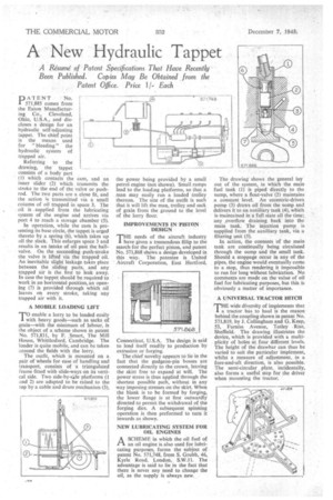
PATENT No. 571,885 comes from the Eaton Manufacturing Co., Cleveland, Ohio, U.S.A., and discloses a design for an hydraulic self-adjusting tappet. The chief point is the means used for " bleeding " the hydraulic system of trapped air.
Referring to the drawing, the tappet consists of a body part (1) which contacts the cam, and an inner slider (2) which transmits the stroke to the end of the valve or pushrod. The two parts are a close fit, and the action is transmitted via a small column of oil trapped in space 3. The oil is .supplied from the lubricating system of the engine and arrives via port 4 to reach a storage chamber (5).
In operation, while the cam is presenting its base circle, the tappet is urged thereto by a spring (6), which takes up all the slack. This enlarges space 3 and results in an intake of oil past the ballvalve. On the succeeding push-stroke the valve is lifted via the trapped oil. An inevitable slight leakage takes place between the sliding parts, and any trapped air is the first to leak away. In case the tappet should be required to work in an horizontal position, an opening (7) is provided through which oil leaves on every stroke, taking any trapped air with it.
A MOBILE LOADING LIFT
T0 enable a lorry to be loaded easily with heavy goods—such as sacks of grain—with the minimum of labour, is the object of a scheme shown in patent No. 571,831, by F. .Smart, The Mill House, Whittlesford, Cambridge. The loader is quite mobile, and can be taken around the fields with the lorry.
The outfit, which is mounted on a pair of wheels for ease of handling and transport, consists of a triangulated frame fitted with slide-ways on its vertical side. Two side-by-s:de platforms (1 and 2) are adapted to be raised to the top by a cable and drum mechanism (3),
the power being provided by a small petrol engine (not shown). -Small ramps lead to the loading platforms, so that a man may easily run a loaded trolley thereon. The size of the outfit is such that it will lift the man, trolley and sack of grain from the ground to the level of the lorry floor.
IMPROVEMENTS IN PISTON DESIGN
VIE needs of the aircraft industry have given a tremendous fillip to the search for the perfect piston, and patent No. 571,868 shows a design developed in this way. The patentee is United Aircraft Corporation, East Hartford,
Connecticut, U.S.A. The design is said to lend itself readily to production by extrusion or forging.
The chief novelty appears to lie in the fact that the gudgeon-pin bosses are connected directly to the crown, leaving the skirt free to expand at will. The power stress is thus applied through the shortest possible path, without in any way imposing stresses on the skirt. When the blank is to be formed by forging, the lower flange is at first outwardly directed to permit the withdrawal of the forging dies. A subSeqtient spinning operation is then performed to turn it inwards as shown.
NEW LUBRICATING SYSTEM FOR OIL ENGINES
ASCHEME in which the oil fuel of an oil engine is also used for lubricating purposes, forms the subject of patent No. 571,748, from S. Grubb, 46, Kyrie Road, London, S.W.11 The advantage is said to lie in the fact that there is never any need to change the oil, as the supply is always new.
The drawing shows the general lay out of the system, in which the main fuel tank (1) is piped directly to the sump, where a float-valve (2) maintains a constant level. An eccentric-driven pump (3) draws oil from the sump and delivers it to an auxiliary tank (4), which is maintained in a full state all the time; any ,overflow draining back into the main tank. The injection pump is supplied from the auxiliary tank, via a filtering unit (5).
In action, the contents of the main tank are continually being circulated through the sump and the small tank. Should a stoppage occur in any of the pipes, the engine would eventually come to a stop, thus rendering it impossible to run for long without lubrication. No comments are made on the value of nil fuel for lubricating purposes, but this is obviously a matter of importance.
A UNIVERSAL TRACTOR HITCH MHE wide diversity of implements that • I a tractor has to haul is the reason behind the coupling shown in patent No. 571,819, by J. Collingham and G. Keep, 53, Fumiss Avenue, TotleY Rise, Sheffield. The drawing illustrates the device, which is provided with a multiplicity of holes at four different levels. The height of the drawbar can thus be varied to suit the particular implement, whilst a measure of adjustment, in a fore-and-aft direction, is also possible. The semi-circular plate, incidentally, also forms a useful step for the driver when mounting the tractor.