


Abridgments of Interesting Patent Specifications.
Page 22
If you've noticed an error in this article please click here to report it so we can fix it.
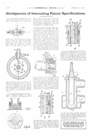
No. 29,526, dated December 31st, 1904. —Liquid-fuel burner.—Willis.--Air is admitted under pressure by a tube (b) to a chamber (a). The incoming air impinges upon a series of vanes (9) rotatably mounted on the fuel nozzle (62). Surrounding the nozzle is a perforated cage (7) operatively connected with the vanes (9), so that it ro tates therewith. The oil supply is controlled by a needle valve (i). As the incoming air rotates the vanes (9) and cage (7), the oil escaping from the cage is thoroughly atomised, and mixes with the air, by which it is carried out through the conduit (c)communicating with the burner.
No. 26,536, dated December 6th, 1904.-Ignition indicator.—Miller.--A vacuum tube (C) is placed in the high-tension cir
coil, so that, when the spark occurs, the vacuum tube is illuminated in the wellknown manner, whereas, if the spark fails, no illumination takes place. The tube shown is made in the form of a spiral, and is protected by a suitable easing.
No. 25,615, dated November 24th, 1904. —Starting Handle.—Barthel.—The starting handle (8) has an extension which projects into a fixed bearing sleeve (to) and is provided with crown total tit). These teeth engage corresponding crown teeth (12) on a ring (9). The ring (g) is free on the motor shaft (1), and is prevented front turning backwards by roller clutches (13). On the screw-threaded end of the motor shaft a ring (3) is rigidly secured, and the crank hub is recessed to receive it, so that bearing faces (7) and (16) are formed between these two members; similarly, a coned bearing face (6) is provided on the shaft (1) and opposed to a corresponding face (17) on the ring (9). A spring (14) tends to draw the ring (9) and starting handle (8) together. Vhen driving forwardly, as indickited by the arrow Figures i and 2, the handle (8) and ring (9) are separated by the crown teeth and forced against the shoulders (6) and ring (3) on the engine shaft so that driving is effected ; this position is shown diagramatically in Fig. 2. If a back-fire occurs, the ring (9) is immediately locked to the bearing (le) by the roller clutches,
and the handle (8) is slightly rotated so that the frictional connection between this and the engine shaft is released, resulting in the parts being freed as shown in Fig. 3. A similar effect is obtained when the engine shaft overruns the starting handle.
No. 1,354, dated January 24th, 1905.— Carburetter.—Campbell.—Hot air is admitted by the inlet (d) to the warming jacket (b), and escapes by the outlet Within the carburetter chamber (a) depends a tube (f), and the air is sucked in through a passage (i) and valve (g). The fuel is admitted by a conduit (h) opening into the valve seat, and the mixture is sucked down the tube (f) into the chamber (a), where it is vaporised by the heat supplied from the jacket 01, and passes to he engine by the outlet (c).