


Servo Operation by Lubricating-oil Pressure
Page 54
If you've noticed an error in this article please click here to report it so we can fix it.
DATEN'T No 449,077 comes from P. J..Riley, of the Riley Engine Co., Ltd., Coventry, and describes a scheme whereby the pressure of the engine lubricating system is used also as a servo-operating force. The accompanying drawing shows a power-operated clutch using this principle. A bore in the tail-end of the crankshaft guides a piston (1) operating in a short but large cylinder formed in the flywheel. A stub (4) attached to the piston. projects into the clutch and forms the operating member. The oil supply to the servo piston is governed externally by a slide-valve (2). controlling supply and returnpassages in the rear main bearing. The most important feature of the patent is a flexible diaphragm (3) which seals -off the cylinder and effectively prevents oil leakage.
Whilst the patent describes the scheme applied to a clutch, this is purely an example ; its use for brakes and gearbox operation is also envisaged.
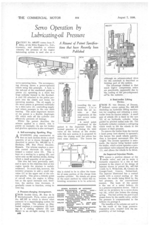
A Self-scavenging Sparking Plug.
A SPARKING plug constructed so 1-1 that on each suction stroke a small quantity of air is drawn through it is described in patent No. 448,884 by F. Bierlaire, 100, Rue Pierre Decoster, Brussels. The scheme employs a movable central electrode on which is formed a -conical valve (3). This is kept on a seating by a spring (2), and opens only on the suction stroke, during which a small quantity of air passes.
This idea has been previously used, and is open to the objection that at low engine speeds the mixture is .unduly weakened. To avoid this, however, the inventor proposes to add. a small cupvalve (1) to the upper end of the central spindle. This gives a definite point of cut-off when the engine is idling, but as the speed increases and, therefore, the suction time decreases, it gradually ceases to function, owing to time lag.
A Pressure-charging Arrangement.
FROM Societe Sebia, 20, Rue de Ia Rochefoucauld, Paris, comes patent No. 447,167 in which is shown what amounts to a supercharging system for petrol engines. The scheme as illustrated employs a compressor (2) leading to a cooling radiator (3) and thence to an air-tight casing (1) stir
B44 rounding the carburetter. T his feeds the air intake, so that evaporation of the fuel occurs under pressure.
A novel point mentioned in the patent is the departure from the normal practice of closing the inlet valve at the bottom of the stroke; with this new system it is proposed to delay the closing until the piston has risen some distance. The reason for
this is stated to be to allow the transfer of some portion of the charge from another cylinder. No details arc given of the exact method by which this interesting occurrence is to be achieved, although although an advance-retard drive for the camshaft is described as forming part of the system.
The advantage claimed is that much high.r compression ratios are practicable, apparently due to the cooling of the pre-compressed air in the radiator, A Semi-trailer Lifting Device.
FROM H. van Doorne, of Deurne, Holland, comes patent No. 449,135 disclosing an hydraulic lifting mechanism for coupling and releasing a semitrailer from its tractor vehicle. A small pair of wheels (3) is fixed to the ram (2) of an hydraulic cylinder, being guided by pivoted radius rods (4). The hydraulic cylinder contains a coil-spring which tends to lift the wheels in the absence of fluid pressure.
To remove the trailer from the tractor a hand pump (not shown) is operated ; this lowers the small wheels quickly; then a low-speed movement lifts the weight. The reverse operation is automatk, the tractor being backed under the trailer, which action operates a pressure-release valve adjacent the pivot pin (1), and allows the wheels to be lifted.
An Improved Injection Nozzle
TO ensure a positive closure of the 1 needle valve, and yet to make it instantly responsive to a rise of fuel pressure is the object of the design of injector shown in patent No. 447,743 (void) by S. Witkowski, 32, Chemin de Grange-Canal, Geneva, Switzerland. The injector illustrated has a central needle with a conical seating at the bottom, the needle being lifted by the fuel pressure, in the conventional manner. The basis of the patent is the use of a metal bellows (1) as a pressure-responsive device. This is held on 'its periphery by a screw-down cap (4), which also houses the closing spring; The fuel arrives via port 2 and passes down by the needle valve, whilst the pressure is communicated to the bellows via passage 3.
The benefits of the scheme are said to be the result of the large pressureresponsive area, coupled with the impossibility of fuel leakage;