


A NEW IDEA IN EPICYCLIC GEAR OPERATION.
Page 64
If you've noticed an error in this article please click here to report it so we can fix it.
A R4sum4 of Recently Published Patent Specifications.
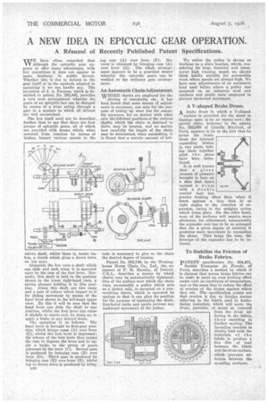
N,IETE have often remarked that V V although the epicyclic gear appears to offer many advantages, with few exceptions it does not appear to make , headway in public favour. Whether this is due to defects in the gear itself or in the methods adopted in operating it we can hardly say. The invention of J. A. Furness, which is described in patent No. 292,445, provides a very neat .arrangement whereby the gears of an epicyclic box can be changed by means of a lever acting through a gate in a manner to which all drivers are Well accustomed.
The box itself need not be described further than to say that there are four groups of epicyclic gears, all of which are provided with drums which, when arrested from rotation by means of brakes, impart various speeds to the driven shaft, whilst there is, inside the box, a clutch which gives a direct drive on top gear.
.Alongside the box runs a shaft which can slide and rock when it is operated upon by the cam of the foot lever. Normally, this shaft is held in the position shown in the lower right-hand view, a spring plunger holding it in this position. Along this shaft are two cams and a pair of collars which impart to it its sliding movement by means of the hand lever shown in the left-hand upper view. By this it will be seen that the hand lever can slide the shaft to any position, whilst the foot lever can cause It slightly to rotate and, by doing so, to apply a brake to any desired drum.
The operation is as follows. The hand lever is brought to first-gear position; which brings cams (A) over lever (C), whilst•the foot lever is depressed ; the release of•the foot lever then causes the Cam to depress the lever and to apply, a brake to the -group of gears, governed by the lever (C). Second gear is produced by bringing cam (B) over lever (D). • Third gear is produced by bringing Cam (B) over lever (E), whilst top or direct drive is produced by bring
94(.3 lug Cam (A) over lever (F). Reverse is obtained by bringing cam (A) over lever' (C). The whole arrangement appears to be a practical means whereby the epicyclic gears can be wedded to the ordinary gate arrangement.
An Automatic Chain Adjustment.
WHERE chains are employed for the driving of camshafts, etc., it has been found that some means of adjustment is necessary, not only for the purpose of taking up wear but for assembly purposes, for no matter with what care the different positions of the various shafts, which the chain is destined to drive, may be located, and no matter how carefully the length of the chain may be determined, when assembling, it is found that a certain amount of lati tude is necessary to give to the chain the desired degree of tension.
Patent No. 282,749, by the Westinghouse Morse Chain Co., Ltd., the assignees of F. M. Hawley, of Detroit, describes a means by which chains may be automatically tightened. One of the pulleys over which the chain runs, presumably a pulley which acts as a jockey only, is mounted on a nonrevolving sleeve, which is operated by springs so that it can alter its position for the purpose of tensioning the chain. Ratcheted racks and pawls prevent any backward movement of the pulley.
We notice the pulley is shown as working on a plain bearing, which, considering its large diameter and consequent high ranninsb speed, we should think hardly suitable for automobile work where speeds are always high. We have, seen adjustments of an automatic kind used before where -a pulley was mounted on an eccentric stud and ratchets and pawls were employed to prevent backward movement., A V-shaped Brake Drum. A brake drum in which a V-shaped
surface is provided for the shoes to impinge upon is by no means new ; the special claim, however," in the patent. No. 282,069 of Camille Martine', of Paris, appears to lie in the fact that lo forms his brakedrum for internal .expanding brakes
in two parts, bolting them, together
after the shoes have been introduced.
It is well known that . a given
amount of pressure brought to bear on a shoe that bears. against a drum with a double conical face has greater braking effect than when it bears against a face that is at right angles to the direction of expan Sian, owing to the wedging action which takes place. On the other hand, wear of the surfaces will require more allowance for adjustment, consequently the expander cam has to be so arranged that for a given degree of rotation it produces more movement in expanding the shoes. This being the case' the leverage of the expander has to be &aced.
To Stabilize the Friction of Brake Fabrics.
PATENT specification No. 264,471,
Societe Francaise On Ferodo, of Paris, describes a method by which it is claimed that woven brake fabrics can be made to exert an even braking effect under van' us,conditions of temperature, and at the same time to reduce the effect of erosion of the drums against which they act. The specification points out that erosion is dm to foreign matter adhering to the fabric used in brakefacing materials, which will score the drum, particles of metal so removed from the drum adhering to the fabric, thus resulting in further scoring. The invention consists in mixing lead with the materials of the fabric to produce a fine film of lead between the fabric and the drum surface. which prevents adhesion between the co-acting surfaces.